Table of Contents
Advertisement
Quick Links
Advertisement
Table of Contents

Subscribe to Our Youtube Channel
Summary of Contents for Quark Eagle 2000
- Page 1 Eagle 2000 ON/STAND-BY Ultra-compact 2 kW FM R.F. Amplifier User’s Manual Revision 1.0 Quark BROADCASTING SRL Via Copernico 2 – 20019 Settimo Milanese (MI) - Italy Tel. +39 02 023288410 – email info@quarkelectronics.it – www.quarkelectronics.it...
-
Page 2: Preliminary Notes
Quark, in their constant commitment to improve the quality of their products, reserve the right to vary the technical features of the same without prior notice. For a full update please visit our web-site www.quarkelectronics.it or contact our local dealer or agent. -
Page 3: Table Of Contents
Eagle 2000 – 2kW FM Broadcasting Amplifier Contents .......................... 5 NTRODUCTION ......................6 ENERAL NFORMATION Safety suggestions ........................6 2.1.a General safety recommendations...................... 6 2.1.b Good practices ..........................7 2.1.c First aid in case of electrical shock ....................7 2.1.d Emergency resuscitation technique....................7 2.1.e Treatment for burns ........................... - Page 4 Eagle 2000 – 2kW FM Broadcasting Amplifier ......................... 29 ENU DESCRIPTION Startup page ..........................29 Working Page........................... 29 Main menu........................... 29 Set Power Output menu......................30 Debug Page menu........................30 9.5.a Analog Inputs menu ........................30 9.5.b Logic Inputs menu........................31 9.5.c Encoder Test menu........................
-
Page 5: Ntroduction
Congratulations for your choice! Eagle 2000 is new-concept, FM broadcasting solid state (MOS-FET), wide-band 2.000 W amplifier. The system is so compact it can be entirely fitted into a 19" 2 unit rack 500 mm depth, which makes Eagle 2000 the ideal solution for medium power repeaters in unattended stations, in N+1 systems and also as a spare amplifier. -
Page 6: General Information
These capacitors should be discharged through a suitable resistor before any circuit points are touched. • Don't take chances. Be fully trained. Quark Broadcasting equipments should be operated and maintained by fully qualified personnel. •... -
Page 7: Good Practices
Eagle 2000 – 2kW FM Broadcasting Amplifier 2.1.b Good practices In maintaining the equipment covered in this manual, please keep in mind the following, standard good practices: • When connecting any instrument (wattmeter, spectrum analyzer, etc.) to a high frequency output, use the appropriate attenuator or dummy load to protect the final amplifiers and the instrument input. -
Page 8: Treatment For Burns
Eagle 2000 – 2kW FM Broadcasting Amplifier Step 4 Put the fingertips of your hand on the Adam's apple, slide them into the groove next to the windpipe. Feel for a pulse. If you cannot feel a pulse or are unsure, move on to the next step. -
Page 9: Symbols Used In This Document
Eagle 2000 – 2kW FM Broadcasting Amplifier Symbols used in this document In order to allow a quick and essential reading, we used symbols which attract immediate attention, and which simply and efficiently advise and inform the user. The symbol of the open hand, stresses a description of the highest importance, which concerns technical intervention, dangerous situations, security warnings, advice and/or information of the highest importance. -
Page 10: Warnings
IMPORTANT: Improper use or installation of this device could cause serious damage to objects and people alike. Therefore, it is essential to rely on an installer who has been previously authorized or approved by Quark Broadcasting, or by our local representative, and that both the user and the installer read the entire manual before carrying out any operation. -
Page 11: Arts Description
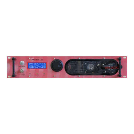
Eagle 2000 – 2kW FM Broadcasting Amplifier A R T S D E S C R I P T I O N Front view Please see the following images to spot and identify the equipment parts and gain confidence with them: ON/STAND-BY ON/STAND-BY button –... -
Page 12: Rear View
- 2 meters length power supply cable. [16] REMOTE I/O – in the next version of Eagle 2000, this DB25 connector will enable the remote control option. [17] GROUND – it allows the connection of the equipment to ground for a safe operation. -
Page 13: Internal Top View - Main Parts Location
Eagle 2000 – 2kW FM Broadcasting Amplifier Internal top view - main parts location Rear side 21/22 Front side [19] Digital encoder – multifunction knob ( 5.7). [20] Display board ( 5.6). [21] Analog board ( 5.4). [22] Control (CPU) board ( 5.3) - installed underneath the analog board. -
Page 14: Ircuits Description
This section’s sole purpose is to provide general explanations about the device operation in order to simplify the maintenance by skilled personnel appointed by Quark. As already mentioned, no internal adjustments are required for normal operation. Tampering with the internal settings makes the warranty null and void. Moreover, could seriously damage the equipment, compromising the guaranteed performance. -
Page 15: Main Power Supply Switch And Power Supply Relay
Even if Eagle 2000 is able to output a (max) 2400W output power (thanks to the use of the 3x800W amplifier modules), it has a rated output power of 2000W, a solution allowing a better reliability. -
Page 16: Control (Cpu) Board
Eagle 2000 – 2kW FM Broadcasting Amplifier Control (CPU) board The control board, located just behind the analog board, stores the software which manages the equipment. Moreover, the built in memory stores the programs used in all models of the Eagle series (please see the bottom note). This board is connected to the various part of the system, thus allowing the CPU to control the equipment operation by sending the appropriate commands or, conversely, to get the data concerning the current functioning and process (e.g. -
Page 17: Analog Board
Eagle 2000 – 2kW FM Broadcasting Amplifier Analog board This board manages all the equipment protections via the output power loop control and the reflected power loop control. On the board there are two trimmers to adjust the direct (RV2) and reflected (RV1) powers shown on the display (e.g. in the working page, 9.2), and a third trimmer (RV3) for the adjustment of the maximum output power level (see the following paragraph for information... -
Page 18: Fans Control Board
Eagle 2000 – 2kW FM Broadcasting Amplifier [51] 48V power supply for the 800W amplifier module #3 – the (black) power resistor is used for the current measurement. [52] 48V power supply for the 800W amplifier module #2 – the (black) power resistor is used for the current measurement. -
Page 19: Digital Encoder (Multifunction Knob)
Eagle 2000 – 2kW FM Broadcasting Amplifier Digital encoder (multifunction knob) This board is located in the back of the front panel near the ON/STAND-BY button [1] and the Analog board ( 5.4). It holds the rotary digital encoder, directly connected to the multifunction knob [7]. The board communicates directly with the Control (CPU) board ( 5.3), which detects the user commands: clockwise rotations, counterclockwise ones, as well as pushbutton operations. -
Page 20: Nstallation
Quark or a local appointed agent/dealer. • Should you encounter any technical problems or be in any doubts about the installation procedure, Quark will be happy to provide its qualified technical support service. We strongly recommend that no interventions must be carried out by personnel not authorized by Quark. -
Page 21: Electrical Conditions
Eagle 2000 – 2kW FM Broadcasting Amplifier that the Eagle 2000 internal fans are low-pressure units and therefore an air extractor on the air exhaust duct in definitely needed. • Air conditioning at 20 – 25 °C would obviously be the best solution. Thermal insulation and efficient ventilation with a thermostat-controlled blower are generally the best solution. -
Page 22: Connecting To The Exciter
Eagle 2000 – 2kW FM Broadcasting Amplifier 6.4.c Connecting to the exciter Warning: The exciting rated power of the amplifier is from 25 to 30W. In order to avoid any damage to the equipment, make sure that the driving power never exceeds 30W. -
Page 23: Asic Operations
Eagle 2000 – 2kW FM Broadcasting Amplifier A S I C O P E R A T I O N S Turning on/turning off 7.1.a First switching on (during installation) The amplifier stores in its memory the operation mode in which it was working before the power supply was turned off or a power line interruption (blackout) took place. -
Page 24: Setting The Display Language
Eagle 2000 – 2kW FM Broadcasting Amplifier Press the multifunction knob to select this menu and move the > cursor on the right of the power value (in this example 100 – see the following note): Gradually turn the multifunction knob until you set the needed output power (clockwise to increase the value, counterclockwise to reduce it). - Page 25 The installation of the amplifier is now completed. A spectrum analysis would be advisable to make sure that no spurious emissions, due to internal or external causes (i.e. intermodulation on the final stage), are generated. Quark wish you success in your work and remind you that we are always available for further information or to solve any specific problem.
-
Page 26: Turning Off
Eagle 2000 – 2kW FM Broadcasting Amplifier 7.1.e Turning off Keep the ON/STANDBY button [1] pressed for a couple of seconds setting the equipment in stand-by mode. Turn off the POWER ON/OFF switch [14] on the rear panel. User’s manual – Page 26 of 66... -
Page 27: Use Of The Menus
Eagle 2000 – 2kW FM Broadcasting Amplifier S E O F T H E M E N U S Use of the multifunction knob The multifunction knob is used to surf the menu with its submenus and set/check their parameters. It can be used in 3 ways: •... -
Page 28: Confirming/Quitting The Settings
Eagle 2000 – 2kW FM Broadcasting Amplifier The described commands are to be considered as standard actions (bear in mind that in some menus they are slightly different). For details about the each single menu and how operate on it Chapt. -
Page 29: Enu Description
4 minutes of inactivity (no actions on the knob), a timer automatically quits the menu restoring the working page. These are the information displayed in it: • QUARK EAGLE rev.1.06: model of the equipment and software revision • Forward Power: forward power level •... -
Page 30: Set Power Output Menu
• Set Clock: sets date and time of the system clock ( 9.9) • Info Page: it shows info about Quark (email, technical support telephone number) ( 9.10). menu Set Power Output Refer to par. 7.1.b in which this menu is already explained. -
Page 31: Logic Inputs Menu
• Module Curr. 3: current of the amplifier module # 3 • Module Curr. 4: current of the amplifier module # 4 (not used with Eagle 2000). To quit and go back to the Debug Page, press the knob. 9.5.b Logic Inputs menu This menu allows to check the proper operation of the ON/STAND-BY button by checking its dedicated contacts of the control board. -
Page 32: Encoder Test Menu
Eagle 2000 – 2kW FM Broadcasting Amplifier 9.5.c Encoder Test menu This menu allows to check the correct operation of the digital encoder connected to the knob. From the Debug Page ( 9.5), select Encoder Test: Press the knob. The Encoder Test menu will be shown: Turn the knob and check if the A and B values are changing. -
Page 33: Set Clock Menu
Info Page This menu shows the contact information of Quark (email, technical support telephone number) in order to get in touch with it in case of support is needed. From the main menu ( 9.3), select the Info Page option: Press the knob. -
Page 34: Et Unction Ize Menu
Eagle 2000 – 2kW FM Broadcasting Amplifier M EN U U N C T I O N I Z E This multilevel technical menu allows to set the equipment as MASTER or SLAVE, set its power size (according to the model), check the time in which it worked in normal operation or other conditions and automatically reduce its output power in certain times. -
Page 35: Function Menu
If the equipment is set as SLAVE, it will stay in stand-by mode until a proper signal will come from the DB25 REMOTE I/O connector [16]. The REMOTE I/O connector will be available only in the next version of Eagle 2000. If you set in SLAVE mode an equipment not provided with such this connector, it won’t be able to properly work. -
Page 36: Show Timers Menu
Eagle 2000 – 2kW FM Broadcasting Amplifier 10.1.c Show Timers menu This option allows to see a page showing the number of working hours, hours with active alarms, stand by hours In the program page ( 10.1), turn counterclockwise the knob scrolling down until Show timers: Press the knob, the Show timers menu is shown: •... -
Page 37: Set A New Password Menu
Eagle 2000 – 2kW FM Broadcasting Amplifier Turn the knob to set the start time, then press the knob to confirm. The cursor will move back on the left of Start: Move the cursor to the left of End h. m. in order to set the end time (see warning at the bottom). - Page 38 Don’t forget to note down the new password, otherwise you won’t be able to access again the Set Function, size menu. To recover a forgotten password, please contact Quark Technical Support. In case you forgot the new password, to recover it please contact Quark Technical Support. User’s manual – Page 38 of 66...
-
Page 39: Maintenance And Warranty
Never change the original settings when the necessary, complex testing equipment and standard calibration are not available. 11.2 Warranty Like all Quark solid state equipment, the Eagle 2000 carries a one year guarantee on all its components with the exclusion of the final R.F. power module, which may be damaged by faulty output connections. -
Page 40: Troubleshooting And Alarms
R O U B L ES H O O T I N G A N D A L A R M S If all instructions described in the current manual are followed, Eagle 2000 will guarantee several years of perfect service. However, should problems arise, see this chapter before contacting the local authorized assistance point. -
Page 41: 12.2 Alarm Messages
Eagle 2000 – 2kW FM Broadcasting Amplifier 12.2 Alarm messages The following table explains the meaning of the alarm messages (which might appear even in normal operation) and indicates some actions to be taken in order to solve the problem. -
Page 42: Echnical Features
Eagle 2000 – 2kW FM Broadcasting Amplifier 13 T E C H N I C A L F E A T U R E S Frequency range ............................87.5 ÷ 108 MHz Modulation..................................FM Input power ................................35W MAX Output power.................................0 - 2000W Spurious emissions ..............................<... -
Page 43: Ndex
Eagle 2000 – 2kW FM Broadcasting Amplifier 14 I N D E X Error messages messages table............41 Alarms LEDs information ........... 40 type of..............40 First aid ..............7 Antenna Forgotten password ........... 38 connection ............. 21 General safety recommendations......6 Basic operations General safety rules........... -
Page 44: P Arts Description
Eagle 2000 – 2kW FM Broadcasting Amplifier general rules ............20 Safety suggestions..........6 Navigating the menu .......... 27 Set Function, Size menu........34 Output power Technical features..........42 adjusting the ............23 Turning off............26 adjusting the Maximum level ......... 17 Turning on............ -
Page 45: Lectrical Mechanical Diagrams And Parts Location
Eagle 2000 – 2kW FM broadcasting Amplifier 15 E L E C T R I C A L M E C H A N I C A L D I A G R A M S A N D P A R T S L O C A T I O N ... - Page 46 Figure 1 – Front view ON/STAND-BY Eagle 2000 – 2kW FM Broadcasting Amplifier User’s manual – Page 46 of 66...
- Page 47 Figure 2 – Rear view GROUND POWER RF IN 230Vac ON/OFF RF OUTPUT 50 OHM REMOTE I/O Eagle 2000 – 2kW FM broadcasting Amplifier User’s manual – Page 47 of 66...
- Page 48 Figure 3 – Top view (open) Eagle 2000 – 2kW FM broadcasting Amplifier User’s manual – Page 48 of 66...
- Page 49 10uF AGND 16MHz 18pF XTAL2 40106 CON2 100nF Title System 1EL104 Size Document Number Design Verify Cod. 1EL104 Scandelli Merlo Date: Thursday, July 12, 2007 Sheet Eagle 2000 – 2kW FM broadcasting Amplifier User’s manual – Page 49 of 66...
- Page 50 ENCB 40106 Title System 1EL104 100nF 100nF 100nF 40106 Size Document Number Design Verify Cod. 1EL104 Scandelli Merlo 100nF 40106 Date: Thursday, July 12, 2007 Sheet Eagle 2000 – 2kW FM broadcasting Amplifier User’s manual – Page 50 of 66...
- Page 51 Figure 6 – Control board (1EL104) – Part layout Eagle 2000 – 2kW FM broadcasting Amplifier User’s manual – Page 51 of 66...
- Page 52 Passo 2,54 U2,U1 74HCT4051 SOIC16 MC34064D3,5 U4,U8 40106 SO14 LMC6482 DS1672 ATmega128 TQFP64 ( 14x14x1 ) MAX202_SON SO16 16MHz HC49 Ribassato 32K768 Cilindro PTH o SMT Eagle 2000 – 2kW FM Broadcasting Amplifier User’s manual – Page 52 of 66...
- Page 53 LlIVELLO =1 STOP BCV27 1EL105 LlIVELLO =0 SPEGNE BC847 Size Document Number Design Verify Cod. 1EL105 Scandelli Merlo P 2.54 Date: Friday, July 25, 2008 Sheet Eagle 2000 – 2kW FM Broadcasting Amplifier User’s manual – Page 53 of 66...
- Page 54 R109 10nF 4.7uF/10V 4.7uF/10V LM25007 100K Title System Schematics Eagle 2000/3000 R112 Size Document Number Design Verify 01EL105 Scandelli Merlo Date: Friday, July 25, 2008 Sheet Eagle 2000 – 2kW FM broadcasting Amplifier User’s manual – Page 54 of 66...
- Page 55 Figure 10 – Logic board (1EL105) – Part layout Eagle 2000 – 2kW FM broadcasting Amplifier User’s manual – Page 55 of 66...
- Page 56 CON2 1 J8 P 2.54 1 L1 100uH 2 Q1,Q8 BC847 6 Q2,Q3,Q4,Q5,Q6,Q7 BCX53 2 Q9,Q10 BCV27 1 RL1 G5V-2-H1-12V 1 RL2 M12 E A 001 Eagle 2000 – 2kW FM Broadcasting Amplifier User’s manual – Page 56 of 66...
- Page 57 2 R103,R104 100R 2 R110,R108 120K 2 TP232,TP234 VBIAS 1 U1 LM25007 2 U2,U3 TLC274 1 U4 TLC272 1 U5 NE5532 6 U6,U7,U8,U9,U10,U11 ZXCT1009-A 1 U12 ICL7662/TO Eagle 2000 – 2kW FM broadcasting Amplifier User’s manual – Page 57 of 66...
- Page 58 Figure 13 – LED board – Part layout Eagle 2000 – 2kW FM Broadcasting Amplifier User’s manual – Page 58 of 66...
- Page 59 Figure 14 – Power Supply unit – Circuit diagram 1/7 Eagle 2000 – 2kW FM broadcasting Amplifier User’s manual – Page 59 of 66...
- Page 60 Figure 15 – Power Supply unit – Circuit diagram 2/7 Eagle 2000 – 2kW FM broadcasting Amplifier User’s manual – Page 60 of 66...
- Page 61 Figure 16 – Power Supply unit – Circuit diagram 3/7 Eagle 2000 – 2kW FM broadcasting Amplifier User’s manual – Page 61 of 66...
- Page 62 Figure 17 – Power Supply unit – Circuit diagram 4/7 Eagle 2000 – 2kW FM broadcasting Amplifier User’s manual – Page 62 of 66...
- Page 63 Figure 18 – Power Supply unit – Circuit diagram 5/7 Eagle 2000 – 2kW FM broadcasting Amplifier User’s manual – Page 63 of 66...
- Page 64 Figure 19 – Power Supply unit – Circuit diagram 6/7 Eagle 2000 – 2kW FM broadcasting Amplifier User’s manual – Page 64 of 66...
- Page 65 Figure 20 – Power Supply unit – Circuit diagram 7/7 Eagle 2000 – 2kW FM broadcasting Amplifier User’s manual – Page 65 of 66...
-
Page 66: User's Manual
Eagle 2000 2kW FM broadcasting Amplifier 16 D E C L A R A T I O N O F O N F O R M I T Y Broadcast Quark di M. Merlo Via Bellincione, 26 - 20134 Milano – Italy Sede Legale P.zza San Giovanni, 30-20080 Cisliano (Mi) Italy...
Need help?
Do you have a question about the Eagle 2000 and is the answer not in the manual?
Questions and answers