Table of Contents
Advertisement
Service Manual
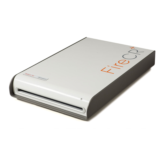
FireCR+
Computed Radiography Scanner
Doc No.: TM-812
Rev: Aug 2013
Part No.: CR-FPM-01-003
3DISC, FireCR, Quantor and the 3D Cube are trademarks of 3D Imaging & Simulations Corp, South
Korea, and its affiliates. All other trademarks are held by their respective owners and are used in an
editorial fashion with no intention of infringement. The data in this publication are for illustration purposes
only and do not necessarily represent standards or specifications, which must be met by 3D Imaging &
Simulations Corp. All information contained herein is intended for guidance purposes only, and
characteristics of the products and services described in this publication can be changed at any time
without notice. Products and services may not be available in your local area. Please contact your local
sales representative for availability information. 3D Imaging & Simulations Corp. strives to provide as
accurate information as possible, but shall not be responsible for any typographical error.
© Copyright 2013 3D Imaging & Simulations Corp, all rights reserved, printed, and published in South
Korea by 3D Imaging & Simulations Corp.
Advertisement
Table of Contents

Subscribe to Our Youtube Channel
Summary of Contents for 3Disc FireCR+
- Page 1 Rev: Aug 2013 Part No.: CR-FPM-01-003 3DISC, FireCR, Quantor and the 3D Cube are trademarks of 3D Imaging & Simulations Corp, South Korea, and its affiliates. All other trademarks are held by their respective owners and are used in an editorial fashion with no intention of infringement.
- Page 2 815, Tamnip-Dong, Yuseong-Gu, Daejeon, Korea Tel : 82-42-931-2100 Fax : 82-42-931-2299 Website : www.3DISCimaging.com E-mail : info@3DISCimaging.com 3DISC Americas 22560 Glenn Dr, Suite 116 Sterling, VA 20164 USA Tel : 1-703-430-6080 E-mail : info@3DISCimaging.com 3DISC Europe Gydevang, 39-41, 3450 Alleroed, Denmark Tel : 45-88-276-650 E-mail : info@3DISCimaging.com...
-
Page 3: Table Of Contents
FireCR Service Manual Computed Radiography Scanner Contents Components ....................... 4 Installation ......................5 Table Top ..............................5 Wall Mount ............................... 6 Connections .............................. 8 Cassette and IP Visual Inspection ......................8 Calibration ......................9 Calibration Geometry ..........................9 Calibration Procedure ..........................10 Reader Diagnostics ................... -
Page 4: Components
FireCR Service Manual Computed Radiography Scanner Components Item FireCR+ Computed Radiography Scanner Fire Kit (Optional Product Identification Card) 14” x 17” Cassette 10” x 12” Cassette 14” x 17” Imaging Plate (Installed in the cassette) 10” x 12” Imaging Plate (Installed in the cassette) IP Extractor USB 2.0 Interface Cable Power Adapter... -
Page 5: Installation
FireCR Service Manual Computed Radiography Scanner Installation Table Top 1. Install on a flat and stable surface. 2. Adjust the feet underneath the scanner to ensure stability. 3. Allow 50cm (20 inches) of free space at the front for cassette insertion and 20cm (8 inches) in the back for cables and power switch access. -
Page 6: Wall Mount
FireCR Service Manual Computed Radiography Scanner Wall Mount 1. Turn reader on its side. Note: Do not turn upside down! 2. Remove adjustable feet. 3. Attach brackets to the scanner. Note: Washers go between the brackets and the bolts. FireCR Installation |... - Page 7 FireCR Service Manual Computed Radiography Scanner 4. Secure wall mount bracket to wall. Note: Make sure that the wall bracket is mounted level. 5. Carefully attach the scanner to the wall bracket. Note: Make sure all four bracket hooks are securely attached to the wall mount bracket.
-
Page 8: Connections
FireCR Service Manual Computed Radiography Scanner Connections Connect power supply and USB cable. Cassette and IP Visual Inspection 1. Remove the IPs from the cassettes by hooking and pulling the plate using the IP Extractor. 2. Visually inspect for defects (air bubbles, scratches, dust, etc.) 3. -
Page 9: Calibration
FireCR Service Manual Computed Radiography Scanner Calibration Calibration Geometry Note: Exposure must always cover the entire cassette. FireCR | Calibration... -
Page 10: Calibration Procedure
FireCR Service Manual Computed Radiography Scanner Calibration Procedure This screen will appear: Step 1: Auto alignment Step 2: Erase Run an erase cycle to remove any residual radiation that may be left on the phosphor. Step 3: Scan Blank Without exposing the cassette, insert it into the reader and press the “Scan Blank” button. Note: Use the same cassette for the entire calibration. - Page 11 FireCR Service Manual Computed Radiography Scanner Understanding the Cal-files: Calibration files can be found in the software folder. Windows Photo Viewer can view the Cal- files. We recommend that you open the “High Dose” calibration of each cassette size to verify an artifact free calibration.
-
Page 12: Reader Diagnostics
FireCR Service Manual Computed Radiography Scanner Reader Diagnostics Scanner Control 1. Software on/off 2. Run manual erasing 3. Run scan 4. Stop scan 5. Select the resolution of scan 6. Laser on/off 7. Eraser on/off 8. Stage control *(current should be “40 & “40”) 9. -
Page 13: Diagnostics Window
FireCR Service Manual Computed Radiography Scanner Diagnostics Window Gauge 1: Rotating mirror RPM (Has to be 1800RPM +/- 10) Gauge 2: Right PSD peak Gauge 3: Right PSD balance Gauge 4: Left PSD peak Gauge 5: Left PSD balance Gauge 6: Internal frame temperature Gauge 7: Mainboard temperature Gauge 8: Eraser temperature Gauge 9: Laser module temperature... -
Page 14: Parts Removal/Replacement
FireCR Service Manual Computed Radiography Scanner Parts Removal/Replacement Top Cover 1. Turn the power off. 2. Unplug the USB cable and power cord. 3. Remove 4 front screws and 3 rear screws from the base plate (2.5mm hex). 4. Pull back cover. FireCR Parts Removal/Replacement |... - Page 15 FireCR Service Manual Computed Radiography Scanner 5. Slowly lift cover from the back. Note: Before removing the cover, disconnect the LED connector underneath. 6. Refit in reverse order. FireCR | Parts Removal/Replacement...
-
Page 16: Internal Cover
FireCR Service Manual Computed Radiography Scanner Internal Cover 1. Remove Top Cover. (Pg. 14) 2. Remove the 6 screws on top of the Internal Cover (#2 Phillips). Note: Some scanners have 10 screws. 3. Disconnect the cassette lock cables from the cassette lock board and feed them through the hole in the middle of the Internal Cover. -
Page 17: Main Board
FireCR Service Manual Computed Radiography Scanner 4. Lift off Internal Cover. 5. Refit in reverse order. Note: There are two grooves on each side of the Internal Cover front. When refitting the Internal Cover, make sure that the cables on both sides go through the upper grooves. -
Page 18: Core Board
FireCR Service Manual Computed Radiography Scanner 4. Unscrew the 6 screws that hold down the board and replace (2.5mm hex). Make sure to connect the cables correctly when reassembling. The cables all have tags corresponding to descriptions on the connectors. 6. -
Page 19: Bldc Board
FireCR Service Manual Computed Radiography Scanner 5. Disconnect the 2 ribbon cables and wire connector. 6. Replace the old core board with a new core board. 7. Reinstall the nuts to secure the core board. 8. Connect the 2 ribbon cables and wire connector. 9. - Page 20 FireCR Service Manual Computed Radiography Scanner 4. Remove 4 screws (2.5mm hex). 5. Reinstall in reverse order. FireCR Parts Removal/Replacement |...
-
Page 21: Cassette Lock Motor Board
FireCR Service Manual Computed Radiography Scanner Cassette Lock Motor Board 1. Remove Top Cover. (Pg. 14) 2. Remove Internal Cover. (Pg. 16) 3. The Cassette Lock Motor Board is located front section of the Fire CR+. 4. Remove the three wire harnesses that connect to the board. Remove four screws holding the board down and lift up. -
Page 22: Optic Plate
FireCR Service Manual Computed Radiography Scanner Optic Plate 1. Remove Top Cover. (Pg. 14) 2. Remove Internal Cover. (Pg. 16) 3. Remove 2 screws from each of the three spring loaded brackets (2.5mm hex). Note: Keep pressure over the spring while removing and re-installing screws. 4. -
Page 23: Aligner Motor
FireCR Service Manual Computed Radiography Scanner Aligner Motor 1. Remove Top Cover. (Pg. 14) 2. Remove Internal Cover. (Pg. 16) 3. Remove Optic Plate. (Pg. 22) 4. Remove internal frame from aluminum housing. (Pg. 30) 5. Remove back cover. FireCR | Parts Removal/Replacement... - Page 24 FireCR Service Manual Computed Radiography Scanner 6. Remove 2 screws from aligner motor (2.5mm hex). 7. Cut cable ties holding wiring harness to cross bar. 8. Remove 3 BLDC bracket screws (2.5mm hex). Note: Wiring harness routes under BLDC bracket and along the side of scanner.
-
Page 25: Y-Axis Motor
FireCR Service Manual Computed Radiography Scanner 10. Unplug wire connector from Main Board. 11. Process is the same for other aligner motor. 12. Reinstall in reverse order. Y-Axis Motor 1. Remove Top Cover. (Pg. 14) 2. Remove Internal Cover. (Pg. 16) 3. - Page 26 FireCR Service Manual Computed Radiography Scanner 4. Take note of wiring harness routing under BLDC bracket. 5. Remove 2 cable clamps along the side of the scanner (#2 Phillips). 6. Unplug wire connector from Main Board. 7. Loosen set screws on belt pulley on motor and axle. Slide both pulleys toward side of scanner until motor pulley slips off end of shaft.
-
Page 27: Fiber Bundle
FireCR Service Manual Computed Radiography Scanner Fiber Bundle 1. Remove Top Cover. (Pg. 14) 2. Remove Internal Cover. (Pg. 16) 3. Remove the 6 screws from the fiber bundle cover (2.5mm hex). 4. Lift off cover. 5. Remove the two screws from the PMT housing (2.5mm Hex). FireCR | Parts Removal/Replacement... - Page 28 FireCR Service Manual Computed Radiography Scanner 6. Loosen PMT connectors. 7. Remove the two screws at the edge of the eraser (#2 Phillips) 8. Pull back eraser. FireCR Parts Removal/Replacement |...
- Page 29 FireCR Service Manual Computed Radiography Scanner 9. Remove the screw on each side of the fiber bundle (2.5mm hex). 10. Lift out fiber bundle. Note: Be careful not to scratch the fibers while pulling out the fiber bundle and note the location of the dowel pin on each side. 11.
-
Page 30: Internal Frame
FireCR Service Manual Computed Radiography Scanner Internal Frame 1. Remove Top Cover. (Pg. 14) 2. Loosen the reset button by removing the two screws attaching it to the base plate (2.5mm hex). 3. Remove six 3mm hex screws connecting the internal frame and the base plate. FireCR Parts Removal/Replacement |... - Page 31 FireCR Service Manual Computed Radiography Scanner 4. Set the reader back down and remove from the bottom the two screws by the speed plate. 5. Remove the internal frame by lifting on the edge of each side. Note: Do not lift on anything but the Internal Cover as pulling on components will damage them! 6.
-
Page 32: Rfid Board
FireCR Service Manual Computed Radiography Scanner RFID Board 1. Remove the Top Cover. (Pg. 14) 2. Remove Internal Frame. (Pg. 30) 3. The RFID board is located in the front mouth of the Fire CR+. 4. Disconnect all three harnesses going to the cassette lock motor. FireCR Parts Removal/Replacement |... -
Page 33: Power Board
FireCR Service Manual Computed Radiography Scanner 5. Remove 4 screws from plexi guides (2.5mm hex). 6. Lift the two plexi guides up and remove the bottom harness going to the RFID Board. 7. Remove the six screws holding the RFID Board to the plexi guides (#2 Phillips). Note: make sure to not lose or drop the spacers. - Page 34 FireCR Service Manual Computed Radiography Scanner 5. Loosen the 3 screws that hold down the Power Board (2.5mm hex). 6. Remove Power Board. 7. Connect all the cables (two switch cables, USB cable and power cable) onto a new Power Board using the tweezers.
-
Page 35: Troubleshooting
PMT. image, assisted by the histogram in the QA menu. If there is still no image, some hardware may need to be exchanged. Contact 3DISC. FireCR | Troubleshooting... - Page 36 This Noisy artifacts is not in high noise but it can reduce the image quality. Replacing the main board usually fixes image artifacts but please contact 3DISC Technical Support so that we will help you to find out the solution.
- Page 37 FireCR Service Manual Computed Radiography Scanner Image artifacts related to a BLDC board and Optic board assembly The BLDC board controls the speed of the Optic mirror motor as well as the RPM. If the BLDC board is defective, the Optic motor will stop. This leads to blank image artifacts as below (Figure3).
- Page 38 FireCR Service Manual Computed Radiography Scanner Figure 5. Example of incorrect alignment of optics mirror. Figure 6. Example of defective optics module (unstable Laser power). Figure 7. Example of horizontal lines from a faulty Y-axis motor or an incorrect stage alignment. To correct this issue, please follow the mechanical troubleshooting manual (readjust the Stage assembly including Timing belt or replace the defective Y-axis motor).
-
Page 39: Mechanical Noise
FireCR Service Manual Computed Radiography Scanner Mechanical Noise Belt Jumping Bent main board plate 1. Remove Top Cover. (Pg. 14) 2. Remove internal frame from base. 3. Remove two spike fastener clips holding the main board plate. 4. Remove 4 hex screws. 5. - Page 40 FireCR Service Manual Computed Radiography Scanner FireCR Troubleshooting |...
Need help?
Do you have a question about the FireCR+ and is the answer not in the manual?
Questions and answers
Hi I need help with callibration ,
To calibrate the 3Disc FireCR+ scanner, follow these steps:
1. Ensure the exposure covers the entire cassette.
2. Auto Alignment: Perform an automatic alignment.
3. Erase: Run an erase cycle to remove any residual radiation from the phosphor.
4. Scan Blank: Insert the cassette without exposing it to complete the calibration process.
This answer is automatically generated