Table of Contents
Advertisement
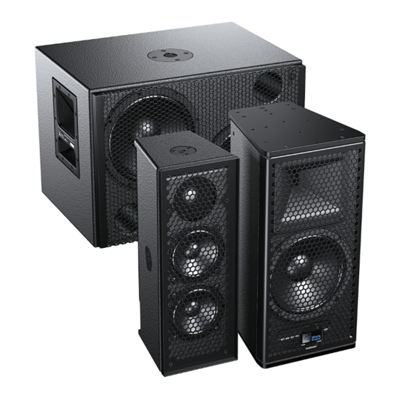
ULTRA XP
OPERATING INSTRUCTIONS
UPJ-1XP Compact VariO Loudspeaker
UPJunior-XP UltraCompact VariO Loudspeaker
UPM-1XP UltraCompact Wide-Coverage Loudspeaker
UPM-2XP UltraCompact Narrow-Coverage Loudspeaker
UMS-1XP UltraCompact Subwoofer
Keep these important operating instructions.
Check www.meyersound.com for updates.
Advertisement
Table of Contents


Need help?
Do you have a question about the UPJ-1XP and is the answer not in the manual?
Questions and answers