
Summary of Contents for GoFit Platinum GFELP01
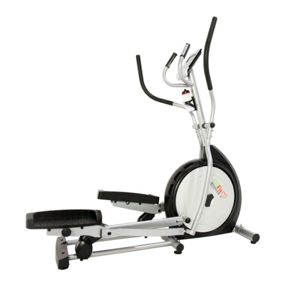
- Page 1 GoFit Platinum Cross Trainer GFELP01 GoFit Platinum Pty Ltd Phone 1800 446 348 fax 1300 446 348 www.gofit.com.au...
-
Page 3: Important Precautions
5) Never operate this appliance if it has a damaged cord or plug, if it is not working properly, if it has been dropped or damaged, or dropped into water. In this case, return the appliance to GoFit Platinum for inspection. 6) Do not carry this appliance by supply cord or use cord as a handle. -
Page 4: Safety Instructions
Keep the GoFit Platinum Cross Trainer indoors, away from moisture and dust. Do not put the GoFit Platinum Cross Trainer in a garage or covered patio, or near water. Make sure before each use that you have enough space around the equipment (at least 1 meter) so that you clear of potential obstructions ie. - Page 5 PRE-ASSEMBLY CHECK LIST ITEM# DESCRIPTION Frame Upper Frame Cover Upright Cover Front Stabilizer Rear Stabilizer Left Rocker Right Rocker 111. Pedal Assembly(L) Pedal Assembly(R) 112. 131. Left Handrail 132. Right Handrail 138. Computer 141. Bottle 142. Bottle Holder Screw Cover 143.
- Page 6 PRE-ASSEMBLY CONTINUED ITEM# DESCRIPTION Wave Washer Ø29xØ21x0.35t Truss Philips Screw M4x12 Wave Washer Ø17.5xØ26x0.3t 115. Nylon Nut M12 116. Truss Hex Screw M12X35 146. Allen Bolt M8x20 147. Washer Ø22xØ9x2t 148. Spring Washer M8x2.0t BK 151. Washer Ø25xØ9x2.0t 152. Truss Hex Screw M8x15 154.
- Page 7 Assembly Screws...
-
Page 8: Assembly Instructions
ASSEMBLY INSTRUCTIONS 1. Assemble Front Stabilizer (#56) to Frame (#1) with Screw (#155), Washers (#157,158) and Acorn Nut (#156). 2. Assemble Rear Stabilizer Cover (#182) to Rear Stabilizer (#63) with Screw (#43). - Page 9 ASSEMBLY INSTRUCTIONS 3. Assemble Rear Stabilizer (#63) to Frame (#1) with Screw (#163), Washers (#157,158) and Acorn Nut (#156). Don't tighten the screws first. 4. Tighten Rear Stabilizer (#63) and Frame (#1) with Screw (#163) and Washers (#157, 158) and then tighten screws in step 3. When using, daub some Lubricate (#172) onto orbit of Rear Stabilizer.
- Page 10 ASSEMBLY INSTRUCTIONS 5. Set Upper Frame Cover (#41) on Upright (#45) and connect Upper Controller Wire (#51) with Middle Controller Wire (#31). Attach Upright to Frame (#1) with Screw (#152) and Washers (#148, 154). 6.Insert Upper Control Wire (#51) into back tie-in of the Computer (#138). Connect Hand Pulse Wire(52) and Wires of the computer and fix the computer to the upright (45) with screw(140)
- Page 11 ASSEMBLY INSTRUCTIONS 7. First cap Wave Washer (#84) on the Frame (#1). Then attach left and right Pedal Assembly (#111, 112) to Frame (#1) with Screw (#146) and Washers (#147, 148) and then cap Screw Cover (#143). When assembly, pay attention to the L" and "R" tabs on pedal assembly.
- Page 12 ASSEMBLY INSTRUCTIONS 9. Aim at the “L" and “R" tabs on Handrail and Rocker and then assemble left and right Rockers (70, 71) to left and right Handrails (131, 132) with Screw (159), Washers (160, 161) and Acorn Nut (162) 10.
- Page 13 ASSEMBLY INSTRUCTIONS 11. Assemble Pedal (#144) to left and right Pedal Assembly (#111, 112) with Screw (#167). 12. Unscrew the screw with washer(49) of upright(45) and fix the bottle holder(142) to the upright with screw(49), then insert the bottle(141) onto the bottle holder.
- Page 14 ASSEMBLY INSTRUCTIONS 13. Adjust frame to level and lift middle adjustment Foot Pad (#69) to let the middle of the frame hang in the air. Then adjust rear adjustment foot pad of the frame to let frame be level and adjust middle adjustment foot pad to floor. Adjust up Nut (#181) with Open Spanner (#180) to tighten adjustment foot pad.
- Page 15 ASSEMBLY INSTRUCTIONS 15. Insert Adapter (#145) into power plug of Frame (#1). Be sure to check the Adapter’s parameters before plug (such as input and output voltage). Assembly is now completed.
- Page 16 TQA Computer Operation Instruction Start-up operation instruction: After power on, the buzzer gives out a beep, at the same time LCD displays for 2 seconds(Fig 1), enter into U1 U4 personal data setting, setting group(Fig 2), sex, age(Fig 3), height, weight press mode, enter into sport menu after confirmation(Fig 4).
- Page 17 Fig 3 1. After entering into sport mode, MANUAL(MAN) on dot matrix is blinking as 1HZ. Press UP & DOWN key to select according to the sequence MANUAL→ PROGRAM(Fig 5)→User Program→H.R.C. (Fig 6)→WATT. When press ENTER / MODE, then enter into this mode. If not select and directly press START key to enter into MANUAL MODE and then START.
- Page 18 Fig 5 2. Set PROGRAM: If selected PROGRAM, then press UP & DOWN key to select P01,P02,P03,P04……,P12 of the PROGRAM. 3. Set LEVEL of PROGRAM: Under START status, it can adjust LEVEL. When adjusting LEVEL, ▲ or ▼ key hasn’t cycle function(Press ▲key can just increase to LEVEL 16, press ▼ key can just decrease to 1).
- Page 19 figure is blinking, after setting, it will be light. While setting, number and letter on LOAD window will display for you to set, LOAD value display 1Hz and be blinking. After setting, press MODE key for confirmation. Time axis of a whole PROGRAM figure has total 20 steps to set so that the PROGRAM can be executed When come to the ninth STEP, scroll bar shifts to left, the rest may be deduced by analogy.
- Page 20 display. ”E-1”means not grip handle tightly. ”E-4”means the body fat percentage is over the setting range(5.0% ~ 50%). The dot matrix displays the symbol of body fat. Press this key and hold it for 2 seconds to reset personal data, after that, enter into fat test directly.
- Page 21 Trainings hints: With buying this fitness equipment you have taken the first step toward improving your fitness. With the help of this item you can add value to your life with improved health, wellbeing and lifestyle. Goal of training: Building of muscles General fitness Endurance Feeling of wellbeing...
- Page 22 Training: Warming up should be done with every sporting activity to decrease the risk or injury. A suggested warm up is a 5-10 minute run on the spot or around the room with a few jumps at each minute interval. Stretching: The following stretches are gentle but effective in waking up your body, stimulating your circulation and making your ankles more flexible.
- Page 24 Phone 1800 446 348 fax 1300 446 348 www.gofit.com.au...
Need help?
Do you have a question about the GFELP01 and is the answer not in the manual?
Questions and answers
What voltage do I need to buy to replace the adapter??
@Rhi for the cross trainer
The required voltage for the GoFit Platinum GFELP01 adapter replacement is not specified in the provided context. It only advises to check the adapter’s parameters, including input and output voltage, before plugging in.
This answer is automatically generated
My startstop button is not working
If the START/STOP button on your GoFit GFELP01 is not working, try the following steps:
1. Perform a TOTAL RESET by pressing and holding the RESET key for 2 seconds. The buzzer will beep, the LCD will display all segments for 2 seconds, then return to the main menu.
2. Check if the machine is properly assembled and all wires, especially the controller wires, are connected securely.
3. Make sure the machine is plugged in and receiving power.
If the button still does not work after these steps, the issue may require technical service.
This answer is automatically generated
I just bought a second hand cross trainer but can not work out where you plug it in. can you please help with this.
Where is the electrical connection on the gofit platinum cross trainer .