Table of Contents
Advertisement
Quick Links
Advertisement
Chapters
Table of Contents

Summary of Contents for ClearView Network Video Recorder
- Page 1 Network Video Recorder Quick Start Guide Version 3.1.0...
-
Page 2: Table Of Contents
Table of Contents ................1 ..................1 ..............1 ..................1 .....................1 ......................2 ......................3 ........................6 ........................6 ..................7 ................8 ..................10 ....................12 PTZ Setup ................12 2.5.1 PTZ Operation ..............13 2.5.2 .....................14 UPNP ..................14 2.6.1 2.6.2 Built-in Switch Setup............15 2.6.3 Remote Device Connection..........15 Short-cut Menu ..............17 2.6.4 Remote Device Info .............18 2.6.5 ................18... - Page 3 ......................22 3.3.1 LAN Login................22 WAN Login ................22 3.3.2 .............23...
- Page 4 Welcome Thank you for purchasing our network video recorder! This quick start guide is designed to be a reference tool for your system. Please open the accessory bag to check the items one by one in accordance with the list below.
- Page 5 Important Safeguards and Warnings 1 Electrical safety All installation and operation here should conform to your local electrical safety codes. We assume no liability or responsibility for all the fires or electrical shock caused by improper handling or installation. 2 Transportation security Heavy stress, violent vibration or water splash are not allowed during transportation, storage and installation.
- Page 6 Please refer to the packing list in the box *...
- Page 7 Note: All the installation and operations here should conform to your local electric safety rules. When you receive the NVR from the forwarding agent, please check whether there is any visible damage. The protective materials used for the package of the NVR can protect most accidental clashes during transportation.
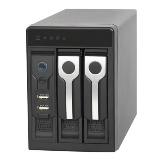
- Page 8 Pull the HDD knob up when you put the HDD Put the knob back after you insert the HDD into the box in case the knob buckle may strike to the SATA board. the front panel. The front panel is shown as in Figure 1-1. Figure 1-1 Please refer to the following sheet for front panel button information.
- Page 9 previous character before the cursor. In motion detection setup, working with Fn and direction keys to realize setup. In text mode, click it to switch between numeral, English character (small/capitalized) and etc. In HDD management interface, you can click it to switch record information...
- Page 10 Port Name Connection Function HDMI High Definition High definition audio and video signal output Media port. It transmits uncompressed high Interface definition video and multiple-channel data to the HDMI port of the display device. VGA video VGA video output port. Output analog video output port signal.
- Page 11 Port Name Connection Function MIC OUT Audio output Audio output port. It is to output the analog port audio signal to the devices such as the sound box. Bidirectional talk output. Audio output on 1-window video monitor. Audio output on 1-window video playback.
- Page 12 Connect the device to the monitor and then connect a mouse and power cable. Click the power button at the rear panel and then boot up the device to view the analog video output. You can use the mouse to implement some GUI operation.
- Page 13 Figure 2-2 Important: For security reason, please modify password after you first login. Within 30 minutes, three times login failure will result in system alarm and five times login failure will result in account lock! After the system booted up, it is in default 24-hour regular mode. You can set record type and time in schedule interface.
- Page 14 Figure 2-3 Tips Copy function allows you to copy one channel setup to another. After setting in channel 1, click Copy button, you can go to interface Figure 2-4. You can see current channel name is grey such as channel 1. Now you can select the channel you wan to paste such as channel 5/6/7.
- Page 15 Default gateway: Here you can input the default gateway. Please note system needs to check the validity of all IPv6 addresses. The IP address and the default gateway shall be in the same IP section. That is to say, the specified length of the subnet prefix shall have the same string. DHCP: It is to auto search IP.
- Page 16 Figure 2-5 Before the operation, please make sure you have properly connected the alarm devices. You can refer to the User’s Manual for reference. Alarm interface is shown as below. See Figure 2-6. Alarm in: Here is for you to select channel number. Event type: There are four types.
- Page 17 Figure 2-6 For the 32-channel series product, the alarm interface and PTZ setup is shown as below. See Figure 2-7 and Figure 2-8. Figure 2-7...
-
Page 18: Ptz Setup
Figure 2-8 Please note: Slight difference may be found in the user’s interface, due to various protocols. Please make sure the speed domes A/B cables are properly connected to the A/B ports of NVR. You have properly set PTZ information. (Main menu->Setting->PTZ). Please switch camera monitor channel to current window. -
Page 19: Ptz Operation
Figure 2-9 If you are connecting to network PTZ, the PTZ type shall be remote. See Figure 2-10. Figure 2-10 After completing all the setups please click save button, system goes back to the previous menu. 2.5.2 PTZ Operation In one window display mode, right click mouse (click “Fn” Button in the front panel or click “Fn” key in the remote control). -
Page 20: Upnp
Please note current command is grey if current series product does not support this function. Double click the PTZ menu head to hide it. Click icon to adjust zoom, focus and iris. Here you can set PTZ direction, speed (step), focus, zoom, iris, preset, tour, pattern, scan, aux call, light, rotation and etc. -
Page 21: Built-In Switch Setup
Figure 2-13 2.6.2 Built-in Switch Setup The built-in switch function is for product of PoE port. From Network->Network Server->Switch, you can set switch IP address, subnet mask, gateway and etc. See Figure 2-14. Figure 2-14 2.6.3 Remote Device Connection In the main menu, click the Remote Device icon to go to the corresponding interface. The remote device interface is shown as in Figure 2-15. - Page 22 Auto: The video whole brightness can adjust automatically within the normal exposure threshold according to different environments. The lower the gain value is, the smaller the noise is. Manual: It is to display manual exposure value. Delete: Please select one device in the Added device list and then click it to remove. Manual add: Click it to add the IPC manually.
-
Page 23: Short-Cut Menu
This series product max supports 32-channel standard definition video/high definition non-real-time video and the transmission rate is 1mbps per channel. It can also max supports 4-channel high definition video and the transmission rate is 8mbps. The delay time of each channel is below 500ms. Model System Performance 4-ch series... -
Page 24: Remote Device Info
Figure 2-18 Figure 2-19 2.6.5 Remote Device Info Please go to the main menu->system info, click the remote device info button to view the detailed information. It includes remote device channel status, connection log and network load and etc. Please refer to the user’s manual for detailed information. - Page 25 Figure 2-20...
- Page 26 Important Slightly difference may be found in the interface due to different series. The following operation is based on 16-channel series device. For the 32-channel series product, there is 32-channel option. This series NVR product support the Web access and management via PC. Web includes several modules: Monitor channel preview, record search, alarm setup, system configuration, PTZ control, monitor window and etc.
- Page 27 address, otherwise it can refresh to the newly added device and memorize the <PoE port>--- <Channel>. If it is your second time to insert the PoE, system can check the saved MAC address according to <Channel>---<IPC mac> map to make sure current IPC has connected or not. If system finds the previous information and the channel is idle, system can map it to the previously used channel.
- Page 28 3.3.1 LAN Login For the LAN mode, after you logged in, you can see the main window. See Figure 3-2. Click the channel name on the left side; you can view the real-time video. Figure 3-2 3.3.2 WAN Login In WAN mode, after you logged in, the interface is shown as below. See Figure 3-3. Figure 3-3 For detailed operation information, please refer to the User’s Manual included in the resources CD.
- Page 29 Toxic or Hazardous Materials or Elements Component Name Cr VI PBDE Sheet Metal(Case) Plastic Parts Panel Circuit Board Fastener Wire and Cable/AC Adapter Packing Material Accessories Note O: Indicates that the concentration of the hazardous substance in all homogeneous materials in the parts is below the relevant threshold of the SJ/T11363-2006 standard.
- Page 30 Network Video Recorder User’s Manual V 3.1.0...
- Page 31 Table of Contents .......................1 ............................1 ............................1 ..........................2 .......................4 ............................4 ............................5 .........................7 ...........................7 2.4.1 Device-end to PC-end ......................7 2.4.2 PC-end to the device-end ....................8 ..........................8 ..........................10 .............................11 .............................11 ........................13 ...........................14 ........................14 ..........................18 4.5.1 HDD Information........................18 4.5.2 BPS............................19 4.5.3 Log............................20 4.5.4 Version ..........................21 4.5.5 Online Users.........................21 4.5.6...
- Page 32 4.5.7.1 Network Test........................23 4.5.7.2 Network Load......................24 ............................24 4.6.1 General ..........................25 4.6.2 Encode ..........................27 4.6.3 Schedule ..........................29 4.6.3.1 Quick Setup.........................30 4.6.4 RS232 ...........................31 4.6.5 Network ..........................31 Network Setting ......................33 4.6.5.1 4.6.5.2 IP Filter.........................33 NTP Setup ........................34 4.6.5.3 4.6.5.4 Multicast........................35 4.6.5.5 PPPoE..........................36 DDNS ...........................36 4.6.5.6 UPNP ...........................38...
- Page 33 4.7.4.5 Stop all channel recording..................67 4.7.5 Account ..........................67 Modify Password ......................68 4.7.5.1 Add/Modify Group ......................69 4.7.5.2 Add/Modify User ......................69 4.7.5.3 4.7.6 Auto Maintenance .......................70 4.7.7 Config Backup........................70 .............................70 ........................72 ............................72 .............................72 ............................75 ........................75 6.1.1 Preparation ...........................75 6.1.2 Log in.............................76 ............................77 6.2.1 Monitor Channel Menu Tree ....................78 6.2.2...
- Page 34 6.4.3 Advanced..........................108 HDD Management ....................108 6.4.3.1 6.4.3.2 Abnormity........................109 6.4.3.3 Alarm I/O........................110 6.4.3.4 Record........................111 Account ........................111 6.4.3.5 6.4.3.6 Snapshot........................113 Auto Maintenance ....................113 6.4.3.7 6.4.3.8 Remote device......................114 6.4.3.9 Preview Control ......................115 6.4.4 Additional Function......................116 IPC Config .........................116 6.4.4.1 6.4.4.2 Auto register......................118 Mobile Config ......................118 6.4.4.3 WIFI Config .......................119 6.4.4.4...
- Page 35 Welcome Thank you for purchasing our network video recorder! This user’s manual is designed to be a reference tool for your system. Please open the accessory bag to check the items one by one in accordance with the list below.
- Page 36 Important Safeguards and Warnings 1 Electrical safety All installation and operation here should conform to your local electrical safety codes. We assume no liability or responsibility for all the fires or electrical shock caused by improper handling or installation. 2 Transportation security Heavy stress, violent vibration or water splash are not allowed during transportation, storage and installation.
- Page 37 Check the following accessories after opening the box Please refer to the packing list in the box *...
- Page 38 This series NVR is a high performance network video recorder. This series product support local preview, multiple-window display, recorded file local storage, remote control and mouse shortcut menu operation, and remote management and control function. This series product supports centre storage, front-end storage and client-end storage. The monitor zone in the front-end can be set in anywhere.
- Page 39 Support network backup, USB2.0 record backup function, the recorded Backup files can be saved in network storage server, peripheral USB2.0 device, burner and etc. Network Supervise NVR configuration and control power via Ethernet. Management Support management via WEB. Support peripheral equipment management such as protocol setup and Peripheral port connection.
- Page 40 el Playback Alarm Input 4/8-ch series product support 4/8-ch alarm input respectively. 3-ch alarm output Alarm Output Relay output. Relay DC 30V 1A AC 125V 0.5A Activation output Including one controllable DC +12V output. 2 built-in SATA ports Storage 1 peripheral eSATA port RS485 port One RS485 port to control PTZ.
- Page 41 The front panel is shown as in Figure 2-1. Figure 2-1 Please refer to the following sheet for detailed information. Name Icon Function Power button Power button, press this button for three seconds to boot up or shut down NVR. One-window monitor mode, click this button to display assistant function: PTZ control and image color.
- Page 42 prompt) Realize other special functions. To connect USB2.0 storage device, USB2.0 mouse, burner and USB2.0 port etc. Power Power indication light. indication light HDD abnormal HDD error occurs or HDD capacity is below specified threshold indication light value, the light becomes red to alert you. Network Network error occurs or there is no network connection, the light abnormal...
- Page 43 Port Name Connection Function HDMI High Definition High definition audio and video signal output Media port. It transmits uncompressed high Interface definition video and multiple-channel data to the HDMI port of the display device. VGA video VGA video output port. Output analog video output port signal.
-
Page 44: Device-End To Pc-End
Port Name Connection Function MIC OUT Audio output Audio output port. It is to output the analog port audio signal to the devices such as the sound box. Bidirectional talk output. Audio output on 1-window video monitor. Audio output on 1-window video playback. -
Page 45: Pc-End To The Device-End
Listening Operation At the device end, speak via the speaker or the pickup, and then you can get the audio from the earphone or sound box at the pc-end. See Figure 2-4. Figure 2-4 2.4.2 PC-end to the device-end Device Connection Connect the speaker or the pickup to the audio output port in the PC and then connect the earphone or the sound box to the first audio input port in the device rear panel. - Page 46 In input box, you can select input methods. Left click the corresponding button on the panel you can input numeral/English character (small/capitalized). Here stands for backspace button. stands for space button. In English input mode: _stands for input a backspace icon and stands for deleting the previous character.
- Page 47 Important Please turn off the power before you replace the HDD. The pictures listed below for reference only. For the first time install, please be aware that whether the HDDs have been installed. You can refer to the Appendix for recommended HDD brand. Please use HDD of 7200rpm or higher.
- Page 48 Connect the device to the monitor and then connect a mouse and power cable. Click the power button at the rear panel and then boot up the device to view the analog video output. You can use the mouse to implement some GUI operation. After device booted up, the system is in multiple-channel display mode.
- Page 49 Recording status Video loss Motion detection Camera lock Preview Control The preview control function has the following features. Support preview playback. In the preview desktop, system can playback previous 5-60 minutes record of current channel. Please go to the Main Menu->General to set real-time playback time. Support drag and play function.
- Page 50 Current selected backup channel has an icon as and the free channel is shown as an icon Once the backup started, you can see the free channel is shown as an icon as Manual Snap Click it to snap manually. Remote device add It is to go to the remote device connection shortcut...
- Page 51 After you logged in, the system main menu is shown as below. See Figure 4-5. There are total seven icons: search, Information, setting, remote device, backup, advanced and shutdown. Move the cursor to highlight the icon, then double click mouse to enter the sub-menu. Figure 4-5 Click search button in the main menu, search interface is shown as below.
- Page 52 Please refer to the following sheet for more information. Name Function Display Here is to display the searched picture or file. window Support 1/4/9/16-window playback. Here you can select to search the picture or the recorded file. You can select to play from the read-write HDD, from peripheral device or from redundancy HDD.
- Page 53 Please note: System max locks 16 files. The size of the locked file shall be less than the 1/4 of the HDD total space. The first 16G of each partition can not be locked. System can only lock one file at one time and can not lock the extra stream. For the file that is writing or overwriting, it can not be locked.
- Page 54 Use the mouse to click one point of the color zone in the time bar, system begins playback. The time bar is beginning with 0 o'clock when you are setting the configuration. The time bar zooms in the period of the current playback time when you are playing the file.
-
Page 55: Hdd Information
Note: All the operations here (such as playback speed, channel, time and progress) have relationship with hardware version. Some series NVRs do not support some functions or playback speeds. Here is for you to view system information. There are total seven items: HDD (hard disk information), BPS (data stream statistics), log, Version, online user, remote device information and network info. -
Page 56: Bps
Figure 4-9 Parameter Function SATA 1-2 here means there are 2 HDDS. When HDD is working properly, system is shown as O. . “_” means there is no HDD. You can view the HDD amount the device connected to; means the second HDD is current working HDD. Type The corresponding HDD property. -
Page 57: Log
Figure 4-10 4.5.3 Log Here is for you to view system log file. System lists the following information. See Figure 4-11. Log types include system operation, configuration operation, data management, alarm event, record operation, log clear and etc. Start time/end time: Pleased select start time and end time, then click search button. You can view the log files in a list. -
Page 58: Version
Figure 4-12 4.5.4 Version Here is for you to view some version information. See Figure 4-13. Channel Alarm in Alarm out System version: Build Date Serial number Figure 4-13 4.5.5 Online Users Here is for you manage online users connected to the local device. See Figure 4-14. You can disconnect one user or block one user if you have proper system right. -
Page 59: Remote Device Information
Figure 4-14 4.5.6 Remote Device Information Here you can view the channel status of the remote device, connection log and etc. Channel status: Here you can view the IPC status of the corresponding channel such as motion detect, video loss, camera masking, alarm and etc. See Figure 4-15. Figure 4-15 Connection log: In this interface, you can search the IPC log information of the corresponding channel. -
Page 60: Network Info
Figure 4-16 4.5.7 Network Info In this interface, you can see network test and network load information. 4.5.7.1 Network Test Network test interface is shown as in Figure 4-17. Destination IP: Please input valid IPV4 address and domain name. Test: Click it to test the connection with the destination IP address. The test results can display average delay and packet loss rate and you can also view the network status as OK, bad, no connection and etc. -
Page 61: Network Load
Figure 4-17 4.5.7.2 Network Load Network load is shown as in Figure 4-18. Here you can view the follow statistics of the device network adapter. Here you can view information of all connected network adapters. The connection status is shown as offline if connection is disconnected. -
Page 62: General
Figure 4-19 Important Please note you need to have the proper right to implement the following operation. 4.6.1 General General setting includes the following items. See Figure 4-20. System time: Here is for you to set system time Date format: There are three types: YYYYY-MM-DD: MM-DD-YYYYY or DD-MM-YYYY. Date separator: There are three denotations to separate date: dot, beeline and solidus. -
Page 63: Figure
Holiday setting: Click it you can see an interface shown as in Figure 4-23. Here you can set holiday date. Please go to the Holidays Period interface to set the holiday date record setup. When you enable Holiday settings and schedule setup at the same time, holiday setting has the priority. -
Page 64: Encode
Figure 4-21 Figure 4-22 Figure 4-23 Figure 4-24 4.6.2 Encode Encode setting includes the following items. See Figure 4-25. Please note some series do not support extra stream. Channel: Select the channel you want. Type: Please select from the dropdown list. There are three options: regular/motion detect/alarm. -
Page 65: And Figure
Resolution: The mainstream resolution type is IPC’s encoding config. Generally there is D1/720P/1080P. Frame rate: It ranges from 1f/s to 25f/s in NTSC mode and 1f/s to 30f/s in PAL mode. Bit rate type: System supports two types: CBR and VBR. In VBR mode, you can set video quality. -
Page 66: Schedule
Figure 4-26 Figure 4-27 Figure 4-28 4.6.3 Schedule In the main menu, from setting to schedule, you can go to schedule menu. See Figure 4-29. Channel: Please select the channel number first. You can select “all” if you want to set for the whole channels. -
Page 67: Quick Setup
menu->Advanced->HDD Management). Please note this function is null if there is only one HDD. Snapshot: You can enable this function to snapshoot image when an alarm occurs. Record types: There are four types: regular, motion detection (MD), Alarm, MD & alarm. Holiday: Highlight the button here, the holiday settings in General interface (Chapter 4.6.1) becomes activated. -
Page 68: Rs232
Figure 4-30 4.6.4 RS232 RS232 interface is shown as below. There are five items. See Figure 4-31. Function: There are various devices for you to select. Console is for you to use the COM or mini-end software to upgrade or debug the program. The control keyboard is for you to control the device via the special keyboard. - Page 69 IP Version: There are two options: IPv4 and IPv6. Right now, system supports these two IP address format and you can access via them. MAC address: The host in the LAN can get a unique MAC address. It is for you to access in the LAN.
-
Page 70: Network Setting
input value shall be 128-digit. It shall not be left in blank. After completing all the setups please click save button, system goes back to the previous menu. Figure 4-32 4.6.5.1 Network Setting Network setting interface is shown as in Figure 4-33. Please draw a circle to enable corresponding function and then double click current item to go to setup interface. -
Page 71: Ntp Setup
Start address/end address: Select one type from the dropdown list, you can input IP address in the start address and end address. Now you can click Add IP address or Add IP section to add. For the newly added IP address, it is in enable status by default. Remove the before the item, then current item is not in the list. -
Page 72: Multicast
Here is a sheet for your time zone setup. City /Region Name Time Zone London GMT+0 Berlin GMT+1 Cairo GMT+2 Moscow GMT+3 New Deli GMT+5 Bangkok GMT+7 Beijing (Hong Kong) GMT+8 Tokyo GMT+9 Sydney GMT+10 Hawaii GMT-10 Alaska GMT-9 Pacific Time(P.T) GMT-8 American Mountain Time(M.T) GMT-7... -
Page 73: Pppoe
-224.0.0.0-239.255.255.255 -“D” address space The higher four-bit of the first byte=”1110” Reserved local multiple cast group address -224.0.0.0-224.0.0.255 -TTL=1 When sending out telegraph -For example 224.0.0.1 All systems in the sub-net 224.0.0.2 All routers in the sub-net 224.0.0.4 DVMRP router 224.0.0.5 OSPF router 224.0.0.13 PIMv2 router... - Page 74 You need a PC of fixed IP in the internet and there is the DDNS software running in this PC. In other words, this PC is a DNS (domain name server). In network DDNS, please select DDNS type and highlight enable item. Them please input your PPPoE name you get from you IPS and server IP (PC with DDNS ) .
-
Page 75: Upnp
Domain name There are two modes: Default domain name and customized domain name. Except default domain name registration, you can also use customized domain name (You can input your self-defined domain name.). After successful registration, you can use domain name to login installed of the device IP. -
Page 76: Wifi Setting
Figure 4-39 Figure 4-40 4.6.5.8 WIFI Setting You can view the WIFI connection status in the Network Setting interface. See Figure 4-41. You can view current connection status and IP address if there is a connection. Figure 4-41 The WIFI interface is shown as below. See Figure 4-42. - Page 77 Auto connect WIFI: Check the box here, system automatically connects to the previous WIFI hotspot. Refresh: You can click it to search the hotspot list again. It can automatically add the information such as the password if you have set it before. Disconnect: Here you can click it to turn off the connection.
-
Page 78: Email
Figure 4-44 WIFI working status: Here you can view current connection status. Please note: After successful connection, you can see WIFI connection icon at the top right corner of the preview interface. When the hotspot verification type is WEP, system displays as AUTO since the device can not detect its encryption type. -
Page 79: Ftp
Title: Please input email subject here. System support English character and Arabic number. Max 32-digit. Receiver: Please input receiver email address here. System max supports 3 email boxes. SSL enable: System supports SSL encryption box. Interval: The send interval ranges from 0 to 3600 seconds. 0 means there is no interval. Health email enable: Please check the box here to enable this function. - Page 80 Figure 4-48 You can use a PC or FTP login tool to test setup is right or not. For example, you can login user ZHY to F TP://10.10.7.7 and then test it can modify or delete H 1 4 0 H 1 4 0 H 1 4 0 H T U folder or not.
-
Page 81: Alarm Center
Figure 4-50 Figure 4-51 4.6.5.11 Alarm center Interface is pre-reserved for the users to develop this function. 4.6.5.12 SNMP SNMP is an abbreviation of Simple Network Management Protocol. It provides the basic network management frame of the network management system. The SNMP widely used in many environments. -
Page 82: Auto Register
Please enable the SNMP function. Use the corresponding software tool (MIB Builder and MG-SOFT MIB Browser. You still need two MIB file: BASE-SNMP-MIB, NVR-SNMP-MIB) to connect to the device. You can get the device corresponding configuration information after successfully connection. Please follow the steps listed below to configure. -
Page 83: Alarm
4) Now you can boot up the proxy server. When you see the network status is Y, it means your registration is OK. You can view the proxy server when the device is online. Important The server IP address can also be domain. But you need to register a domain name before you run proxy device server. - Page 84 Alarm output: The number here is the device alarm output port. You can select the corresponding ports(s) so that system can activate the corresponding alarm device(s) when an alarm occurred. Latch: When the anti-dither time ended, the channel alarm you select in the alarm output may last the specified period.
- Page 85 Figure 4-54 Figure 4-55 Figure 4-56...
-
Page 86: Detect
Figure 4-57 4.6.7 Detect Go to Detect Menu In the main menu, from Setting to Detect, you can see motion detect interface. See Figure 4-58.There is three detection types: motion detection, video loss, camera masking. The video loss has no detection region and sensitivity setup and camera masking has no detection region setup. - Page 87 Menu->Setting->Schedule) and schedule record in manual record interface(Main Menu->Advanced->Manual Record) PTZ activation: Here you can set PTZ movement when an alarm occurs. System can go to a preset, when there is an alarm. Click “select” button, you can see an interface is shown as in Figure 4-60.
-
Page 88: Video Loss
Figure 4-59 Figure 4-60 Figure 4-61 Figure 4-62 4.6.7.2 Video Loss In Figure 4-58, select video loss from the type list. You can see the interface is shown as in... -
Page 89: Camera Masking
Figure 4-63.This function allows you to be informed when video loss phenomenon occurred. You can enable alarm output channel and then enable show message function. You can refer to chapter 4.6.7.1Motion detect for detailed information. Tips: You can enable preset/tour/pattern activation operation when video loss occurs. Figure 4-63 4.6.7.3 Camera Masking When someone viciously masks the lens, or the output video is in one-color due to the... -
Page 90: Ptz
Figure 4-64 4.6.8 PTZ Note: All the operations here are based on PELCOD protocol. For other protocols, there might be a little difference. Cable Connection Please follow the procedures below to go on cable connection Connect the dome RS485 port to NVR 485 port. Connect dome video output cable to NVR video input port. - Page 91 Figure 4-66 After completing all the setting please click save button. In one window display mode, right click mouse (click “Fn” Button in the front panel or click “Fn” key in the remote control). Click Pan/Tilt/Zoom, the interface is shown as below. See Figure 4-67. Here you can set the following items: Step: value ranges fro 1 to 8.
-
Page 92: Display
Iris Close Open 4.6.9 Display Display setup interface is shown as below. See Figure 4-69. Transparency: Here is for you to adjust transparency. The value ranges from 128 to 255. Channel name: Here is for you to modify channel name. System max support 25-digit (The value may vary due to different series). -
Page 93: Default
Figure 4-70 4.6.10 Default Click default icon, system pops up a dialogue box. You can highlight to restore default factory setup. Select all General Encode Schedule RS232 Network Alarm Detect Pan/tilt/zoom Display Channel name Please highlight icon to select the corresponding function. After all the setups please click OK button, system goes back to the previous menu. -
Page 94: Built-In Switch Setup
Figure 4-71 4.6.11.2 Built-in Switch Setup The built-in switch function is for product of PoE port. From Network->Network Server->Switch, you can set switch IP address, subnet mask, gateway and etc. See Figure 4-72. Figure 4-72 4.6.11.3 Remote Device In the main menu, click the Remote Device icon to go to the corresponding interface. See Figure 4-73. - Page 95 IPC config: Double click the on the IPC config column, you can go to the IPC setup interface. See Figure 4-75. Gain mode: It is to set video noise. Check Auto, system automatically sets video gain. Check Manual, you can set gain threshold, brightness and etc. Gain threshold: Here is for you to set gain value.
- Page 96 Figure 4-75 Click the Manual Add button; you can go to the following interface. See Figure 4-76. It can also max supports 4-channel high definition video and the transmission rate is 8Mbps. The delay time of each channel is below 500ms. Model System Performance 4-ch series...
-
Page 97: Short-Cut Menu
Figure 4-76 4.6.11.4 Short-cut Menu In the preview interface, for the channel of no IPC connection, you can click the icon “+” in the centre of the interface to quickly go to the Remote Device interface. See Figure 4-77 and Figure 4-78. -
Page 98: Hdd Management
Figure 4-78 Double click advanced icon in the main window, the interface is shown as below. See Figure 4-79.There are total eight function keys: HDD management, alarm output, abnormity, manual record, account, auto maintenance, TV adjust and video matrix. Figure 4-79 4.7.1 HDD Management Here is for you to view and implement hard disk management. - Page 99 HDD operation: You can select HDD mode from the dropdown list such as read-only or you can erase all data in the HDD. Please note system needs to reboot to get all the modification activated. Figure 4-80 Figure 4-81 For the HDD group setup operation, please note: Each channel’s records can be stored into the specified HDD Group.
- Page 100 HDD Setting Click the button “HDD Settings” at the top right corner of the Figure 4-80, system will pop up an interface as below. See Figure 4-82. The number of hard disk from 1 to 2 is shown in the “HDD No.” column (It is to show the max HDD amount you can install).
-
Page 101: Abnormality
in the specified HDD. You can remove the HDD and then check the channel can record or not. You can see the channel does not record and you can not search the previous record now. Figure 4-83 4.7.2 Abnormality Abnormality interface is shown as in Figure 4-84. Event type: There are several options for you such as disk error, no disk, disconnection, IP conflict and etc. -
Page 102: Manual Record
Please highlight icon to select the corresponding alarm output. After all the setups please click OK button, system goes back to the previous menu. See Figure 4-85. Figure 4-85 4.7.4 Manual Record Note: You need to have proper rights to implement the following operations. Please make sure the HDD has been properly installed. -
Page 103: Enable All Channel Recording
recording status. You can use mouse or direction key to highlight channel number. See Figure 4-87. Figure 4-87 4.7.4.4 Enable all channel recording Highlight below All, you can enable all channel recording. All channel schedule record Please highlight “ALL” after “Schedule”. See Figure 4-88. When system is in schedule recording, all channels will record as you have previously set (Main menu->Setting->Schedule). -
Page 104: Stop All Channel Recording
Figure 4-89 4.7.4.5 Stop all channel recording Please highlight “ALL” after “Stop”. See Figure 4-90. System stops all channel recording no matter what mode you have set in the menu (Main menu->Setting->Schedule) Figure 4-90 4.7.5 Account Here is for you to implement account management. See Figure 4-91. Here you can: Add new user Modify user Add group... -
Page 105: Modify Password
The user name and group name can consist of eight bytes. One name can only be used once. There are four default users: admin/888888/666666 and hidden user “default”. Except user 6666, other users have administrator right. Hidden user “default” is for system interior use only and can not be deleted. When there is no login user, hidden user “default”... -
Page 106: Add/Modify Group
4.7.5.2 Add/Modify Group Click add group button, the interface is shown as below. See Figure 4-93. Here you can input group name and then input some memo information if necessary. There are total 60 rights such as control panel, shut down, real-time monitor, playback, record, record file backup, PTZ, user account, system information view, alarm input/output setup, system setup, log view, clear log, upgrade system, control device and etc. -
Page 107: Auto Maintenance
4.7.6 Auto Maintenance Here you can set auto-reboot time and auto-delete old files setup. You can set to delete the files for the specified days. See Figure 4-95. You can select proper setup from dropdown list. After all the setups please click save button, system goes back to the previous menu. Figure 4-95 4.7.7 Config Backup The configuration file backup interface is shown as below. - Page 108 If you shut down the device, there is a process bar for your reference, system waits for 3 seconds and then shut down (You can not cancel). Please note, sometimes you need to input the proper password to shut down the device. Figure 4-97...
- Page 109 Quick configuration tool can search current IP address, modify IP address. At the same time, you can use it to upgrade the device. Please note the tool only applies to the IP addresses in the same segment. Double click the “ConfigTools.exe” icon, you can see an interface is shown as in Figure 5-1. In the device list interface, you can view device IP address, port number, subnet mask, default gateway, MAC address and etc.
- Page 110 Select the “Open Device Web” item; you can go to the corresponding web login interface. See Figure 5-3. Figure 5-3 If you want to modify the device IP address without logging in the device web interface, you can go to the configuration tool main interface to set. In the configuration tool search interface (Figure 5-1), please select a device IP address and then double click it to open the login interface.
- Page 111 Figure 5-5 For detailed information and operation instruction of the quick configuration tool, please refer to the Quick Configuration Tool User’s Manual included in the resources CD.
-
Page 112: Preparation
The device web provides channel monitor menu tree, search, alarm setup, system setup, PTZ control and monitor window. 6.1.1 Preparation Before log in, please make sure: Network connection is right NVR and PC network setup is right. Please refer to network setup(main menu->setting->network) Use order ping ***.***.***.***(* NVR IP address) to check connection is OK or not. -
Page 113: Log In
or not. If system finds the previous information and the channel is idle, system can map it to the previously used channel. Otherwise system goes to the next step. Thirdly, according to the <PoE port>---<Channel> map, system can know the previous mapping channel of current PoE port. - Page 114 Figure 6-2 IE Safety Setup After installation, the interface is shown as below. See Figure 6-3. Figure 6-3 Login interface Please input your user name and password. Default factory name is admin and password is admin. Note: For security reasons, please modify your password after you first login.
-
Page 115: Monitor Channel Menu Tree
For the LAN mode, after you logged in, you can see the main window. See Figure 6-4. Figure 6-4 Main Interface There are six sections: Section 1: Monitor channel menu tree Section 2: System menu Section 3: PTZ control Section 4: Video setup and other setup Section 5: Preview window Section 6: Monitor window switch 6.2.1 Monitor Channel Menu Tree... - Page 116 Figure 6-5 Monitor Channel Menu Tree Please refer to the following sheet for detailed information. Parameter Function CAM 1 to CAM channel 1 to channel 16 Open all /close Click this button to open all video channels. Once all video channels are open, it becomes close all button. Start Dialogue You can click this button to enable audio talk.
- Page 117 The Web can playback the saved (Extension name is dav) files in Local play the PC-end. Click local play button, system pops up the following interface for you to select local play file. See Figure 6-6. Figure 6-6 Refresh Click this button to refresh monitor channel name. Please left click one monitor to view real-time video, the monitor window is shown as in Figure 6-7.
-
Page 118: System Menu
Resize or switch to full screen mode. Change show mode When you click local record button, the system begins Local record recording. The recorded file is saved to system folder: \ RecordDownload(default). You can snapshoot important video. All images are Snapshot memorized in system folder: \ picture download (default). - Page 119 You can click this icon to display or hide the PTZ control platform. Figure 6-10 PTZ Interface Click PTZ set button, the interface is shown as in Figure 6-11. Figure 6-11 PTZ Setup...
-
Page 120: Color And More Setup
Please refer to the following sheet for PTZ setup information. Parameter Function Move the camera to you desired location and then click left limit Scan button. Then move the camera again and then click right limit button to set a right limit. Use direction keys to move the camera to your desired location and Preset then input preset value. -
Page 121: In Wan Mode, After You Logged In, The Interface Is Shown As Below. See Figure
operation here It is to adjust monitor video contrast ness. applies to WEB end only. It is to adjust monitor video saturation. It is to adjust monitor video hue. Reset Restore system default value. Click more button, the interface is shown as in Figure 6-13. Figure 6-13 Color and More Please refer to the following sheet for detailed information. - Page 122 Figure 6-14 Please refer to the following contents for LAN and WAN login difference. 1) In the WAN mode, system opens the main stream of the first channel to monitor by default. The open/close button on the left pane is null. 2) You can select different channel and different monitor mode at the bottom of the interface.
-
Page 123: System Information
main stream. A stands for 4) When you switch from Monitor to Search or Configuration, system pops a dialogue box asking you leave current interface or not. See Figure 6-16.Click the OK button, system will close current monitor window. For example, you click the Config button when you are monitoring, system pos up a following dialogue. -
Page 124: Hdd Information
Figure 6-17 Version Information 6.4.1.2 HDD information Here you can view local storage status such as free capacity and total capacity. See Figure 6-18. Figure 6-18 HDD Information 6.4.1.3 Log Here you can view system log. See Figure 6-19... -
Page 125: System Configuration
Figure 6-19 Log Please refer to the following sheet for log parameter information. Parameter Function Log types include: system operation, configuration operation, data Type management, alarm event, record operation, user management, log clear and file operation. Set time to start search. Start time Set time to finish search Finish time... - Page 126 Figure 6-20 General Setup Figure 6-21 DST Figure 6-22 DST Please refer to the following sheet for detailed information. Parameter Function Here is for you to modify system time. Please click Save button after System Time your completed modification Sync PC You can click this button to save the system time as your PC current time.
-
Page 127: Encode
Please select separator such as – or /. Data Separator There are two options: 24-H and 12-H. Time Format Here you can set day night save time begin time and end time. See Figure 6-21and Figure 6-22. Language Here you can view the system current language. You can select from the dropdown list. -
Page 128: Schedule
For the main stream, recorded file only contains video by default. You need to draw a circle here to enable audio function. Audio / video For extra stream, you need to draw a circle to select the video first and then select the audio if necessary. - Page 129 Figure 6-25 Schedule Time Figure 6-26 Copy Figure 6-27 Please refer to the following sheet for detailed information. Parameter Function Please select a channel first. Channel...
-
Page 130: Rs232
Parameter Function Pre-record Please input pre-record value here. When alarm record or motion detection record occurs, system can record the several seconds video before activating the record operation into the file. (Depends on data size). Setup In Figure 6-24, click set button, you can go to the corresponding setup interface. -
Page 131: Network
Parameter Function RS232 There is only one option COM 01, corresponding to RS232. Console is for debug. Function Control keyboard: Switch between RS232 and control keyboard. Network keyboard: COM control protocol. You can use network keyboard to control NVR via COM. Transparent COM: Network user can communicate with RS232 COM device. - Page 132 Parameter Function MAC Address The host in the LAN can get a unique MAC address. It is for you to access in the LAN. It is read-only. IP Address Here you can use up/down button ( ) or input the corresponding number to input IP address.
- Page 133 Function Parameter PPPOE Remote Input the user name and password which ISP(Internet service supplier) host provided and chose enable. Reboot system after configuration is saved and the device will auto connect to Internet. The IP address is the WAN IP. There are two conditions for reboot, 1.
- Page 134 Parameter Function Input email subject here. Max 32-digit. Subject Input receiver email address here. Max input three addresses. Address Please input the send interval value here. Interval DDNS The DDNS interface is shown as in Figure 6-32. Figure 6-32 DDNS Please refer to the following sheet for detailed information.
- Page 135 works with the device from the manufacturer so that it can add the extension function. 2) Function Introduction The private DDNS client has the same function as other DDNS client end. It realizes the bonding of the domain name and the IP address. Right now, current DDNS server is for our own devices only.
- Page 136 Figure 6-34 NAS Setup Please refer to the following sheet for detailed information. Parameter Function Please select network storage protocol and then enable NAS enable NAS function. The network storage protocol includes FTP. Server IP Input remote storage server IP address. Input Remote storage server port number.
- Page 137 Here you can realize network time synchronization. Please enable current function and then input server IP, port number, time zone and time. Figure 6-35 NTP Please refer to the following sheet for detailed information. Parameter Function Enable Enable NTP function or not. Server IP Server IP address Port...
- Page 138 Figure 6-36 Alarm Centre UNPN Go to the UPnP interface, you can see an image is shown as in Figure 6-37. It allows you to establish the mapping relationship between the LAN and the public network. Here you can also add, modify or remove UPNP item. Figure 6-37 UNPN SNMP The SNMP interface is shown as in Figure 6-38.
-
Page 139: Alarm
Please refer to chapter 4.6.5.12 SNMP for detailed information. Figure 6-38 SNMP 6.4.2.6 Alarm Alarm setup interface is shown as in Figure 6-39. Figure 6-39 Alarm Setup... - Page 140 Figure 6-40 PTZ Setup Figure 6-41 Please refer to the following sheet for detailed information. Parameter Function Event type: There are four types. Local input/network input/IPC Event Type external/IPC offline alarm. Local input alarm: The alarm signal system detects from the alarm input port.
-
Page 141: Detect
Parameter Function There are two options: normal open and normal close. NO becomes Type activated in low voltage, NC becomes activated in high voltage. Period Alarm record function becomes activated in the specified periods. There are six periods in one day. Please draw a circle to enable corresponding period. - Page 142 signal which meets the senility standard that is previously set. See Figure 6-42.
-
Page 143: Ptz
Figure 6-42 Detect Please refer to the following sheet for detailed information. Parameter Function Event type Motion detect, video loss and video masking Select a channel from the dropdown list to set motion detect, video loss and vid Channel masking function. Sensitivity System supports 6 levels. -
Page 144: Default & Backup
Please note, before operation please make sure you have set speed dome address and the NVR and speed dome connection is OK. Figure 6-43 PTZ Please refer to the following sheet for detailed information. Parameter Function You can select monitor channel from the dropdown list. . Channel Select the corresponding dome protocol.(such as PELCOD) Protocol... -
Page 145: Advanced
Figure 6-44 Default and Backup Please refer to the following sheet for detailed information. Parameter Function Select All Restore factory default setup. Export Export system configuration to local PC. Configuration Import Import configuration from PC to the system. Configuration 6.4.3 Advanced 6.4.3.1 HDD Management Please select the storage device first and then you can see the items on your right become valid. -
Page 146: Abnormity
Please refer to the following sheet for detailed information. Parameter Function Format Clear data in the HDD. Read/write Set current HDD as read/write Read only Set current HDD as read. Redundant Set current HDD as redundant HHD. Recover Fix the HDD error. Right now the device does not support this function. -
Page 147: Alarm I/O
Parameter Function Event The abnormal events include: no disk, no space, disk error, offline, IP Type conflict. You need to draw a circle to enable this function. Threshold: It refers to the HDD free space threshold. Normal The corresponding alarm output channel when an alarm occurs. The alarm output channel may vary. -
Page 148: Record
Please refer to the following sheet for detailed information. Parameter Function Alarm output The alarm output channel may vary. The interface here is for reference only. Please click the corresponding number and then click the trigger button. Trigger Enable/disable alarm output. Please note once you activate an alarm manually, you need to click the output channel number again and then click trigger button to disable it. - Page 149 Figure 6-50 Account Figure 6-51 Add user Please refer to the following sheet for detailed information. Parameter Function User Input the user name of the new established account. Reusable The reusable account means that this account can be used in more than one PC at the same time.
-
Page 150: Snapshot
Password Input the password of the new established account. Confirm Input the password of the new established account again. Group Select the group which the new account belongs to. Memo Memo about the new account Authority/All User can select all to entitle this account to all authorities or set authority of each item respectively. -
Page 151: Remote Device
Figure 6-53 Auto Maintenance 6.4.3.8 Remote device Remote device interface is shown as in Figure 6-54. Figure 6-54 Remote device... -
Page 152: Preview Control
Figure 6-55 Manual Add Please refer to the following sheet for detailed information. Parameter Function Remote device Here you can see searched remote device name, IP address, TCP port information and manufacturer name. Channel Please select the local device channel number to connect to the remote device. -
Page 153: Additional Function
Figure 6-56 Preview Control 6.4.4 Additional Function 6.4.4.1 IPC Config IPC configuration interface is shown as in Figure 6-57. Here you can set gain, iris, brightness, contrastness, hue, saturation BLC and etc of the network camera. Figure 6-57 IPC Config Please refer to the following sheet for detailed information. - Page 154 Parameter Function Brightness It is to adjust monitor window bright. The value ranges from 0 to 100. The default value is 50. The larger the number, the bright the video is. When you input the value here, the bright section and the dark section of the video will be adjusted accordingly.
-
Page 155: Auto Register
Mirror It is to switch video left and right limit. This function is disabled by default. Flip It is to switch video up and bottom limit. This function is disabled by default. Please note the video resolution shall be 720P or lower when it is to flip 90°. -
Page 156: Wifi Config
Figure 6-59 Mobile Setup 6.4.4.4 WIFI Config The WIFI interface is shown as in Figure 6-60. Here you can view WIFI connection status. System displays as no connection if there is no connection. You can view connection status and IP address if there is a connection. See Figure 6-61. - Page 157 Figure 6-61 Please refer to the following sheet for detailed information. Parameter Function Refresh Search hotspot again and system can automatically add the information such as password (If there is any record of the hotspot.) WIFI working Here you can view current connection status. information You can view connection status and IP address if there is a connection.
- Page 158 Figure 6-62 Then please click search button, you can see the corresponding files in the list. See Figure 7-61. Figure 6-63 Select the file(s) you want to download and then click download button, system pops up a dialogue box shown as in F igure 7-62, then you can specify file name and path to download the X 4 8 0 H 4 8 0 H 4 8 0 H file(s) to your local pc.
- Page 159 Figure 6-64 Load more It is for you to search record or picture. You can select record channel, record type and record time to download. See Figure 6-65. Figure 6-65 In Figure 6-65, there is a remote back pane at the left bottom of the pane. It allows you to backup the record or picture to your local USB2.0 storage media via the Web remotely.
- Page 160 Figure 6-66 Now you can see system begins download and the download button becomes stop button. You can click it to terminate current operation. At the bottom of the interface, there is a process bar for your reference. Click alarm function, you can see an interface is shown as in Figure 6-67. Here you can set device alarm type and alarm sound setup.
- Page 161 Figure 6-67 Alarm Please refer to the following sheet for detailed information. Type Parameter Function Alarm Video loss System alarms when video loss occurs. Type Motion detection System alarms when motion detection alarm occurs, Disk full System alarms when disk is full. Disk error System alarms when disk error occurs.
- Page 162 Type Parameter Function Sound pop up System sends out alarm sound when an alarm occurs. You can specify as you wish. Path Here you can specify alarm sound file. Click about button, you can view the web information. See Figure 6-68. Figure 6-68 About Click log out button, you can go back to log in interface.
- Page 163 1. Device can not boot up properly. There are following possibilities: Input power is not correct. Power connection is not correct. Power switch button is damaged. Program upgrade is wrong. HDD malfunction or something wrong with HDD ribbon. Seagate DB35.1 DB35.2 SV35 or Maxtor 17-g has compatibility problem. Please upgrade to the latest version to solve this problem.
- Page 164 Device color or brightness setup is not correct. 6. Can not search local records. There are following possibilities: HDD ribbon is damaged. HDD is broken. Upgraded program is not compatible. The recorded file has been overwritten. Record function has been disabled. 7.
- Page 165 PTZ decoder and device address is not compatible. When there are several decoders, please add 120 Ohm between the PTZ decoder A/B cables furthest end to delete the reverberation or impedance matching. Otherwise the PTZ control is not stable. The distance is too far. 12.
- Page 166 System uses too much CPU resources. Please stop record first and then begin backup. Data amount exceeds backup device capacity. It may result in burner error. Backup device is not compatible. Backup device is damaged. 17. Keyboard can not control device. There are following possibilities: Device serial port setup is not correct Address is not correct...
-
Page 167: Daily Maintenance
There is no DivX503Bundle.exe control when you play the file transformed to AVI via media player. No DivX503Bundle.exe or ffdshow-2004 1012 .exe in Windows XP OS. 23. I forgot local menu operation password or network password Please contact your local service engineer or our sales engineer for help. We can guide you to solve this problem. - Page 168 Calculate total capacity needed by each device according to video recording (video recording type and video file storage time). Step 1: According to Formula (1) to calculate storage capacity that is the capacity of each channel needed for each hour, unit Mbyte. 3600 1024 In the formula:...
- Page 169 Manufacturer Series Model Capacity Port Mode Seagate Seagate SV35.1 ST3250824SV 250G SATA Seagate Seagate SV35.1 ST3500641SV 500G SATA Seagate Seagate SV35.2 ST3250820SV 250G SATA Seagate Seagate SV35.2 ST3320620SV 320G SATA Seagate Seagate SV35.2 ST3500630SV 500G SATA Seagate Seagate SV35.2 ST3750640SV 750G SATA Seagate...
- Page 170 Seagate Seagate Pipeline ST3500414CS 500G SATA Seagate Seagate Pipeline ST3500312CS 500G SATA Seagate Seagate Pipeline ST31000424CS SATA Seagate Seagate Pipeline ST31000322CS SATA Seagate Seagate Pipeline ST1000VM002 SATA Seagate Seagate Pipeline ST1500VM002 Seagate Seagate Pipeline ST2000VM002 SATA Seagate Seagate Pipeline ST2000VM003 SATA Seagate Seagate...
- Page 171 Constellation ES Seagate Seagate ST500NM0051 500G SATA Constellation ES Seagate Seagate ST33000650NS SATA Constellation ES.2 Seagate Seagate ST32000645NS SATA Constellation ES.2 Seagate Seagate ST33000651NS SATA Constellation ES.2 Seagate Seagate ST32000646NS SATA Constellation ES.2 Seagate Seagate ST33000652NS SATA Constellation ES.2 Seagate Seagate ST32000647NS SATA...
- Page 172 Digital Westem WD AV—AVJS WD3200AVJS-63WDA0 320G SATA Digital Westem WD AV—AVJS WD5000AVJS-63YJA0 500G SATA Digital Westem WDAV-GP—AVCS WD5000AVCS-63H1B1 500G SATA Digital Westem WDAV-GP—AVCS WD7500AVCS-63ZLB0 750G SATA Digital Westem WDAV-GP—AVCS WD3200AVCS 320G SATA Digital Westem WDAV-GP—AVCS WD2500AVCS 250G SATA Digital Westem WDAV-GP—EVCS WD10EVCS-63ZLB0 SATA...
- Page 173 Digital Westem WD AV-GP WD20EURS SATA Digital Westem WD AV-GP WD15EURS 1.5T SATA Digital Westem WD AV-GP WD10EURS SATA Digital Westem WD AV-GP WD10EURX SATA Digital Westem WD AV-GP WD7500AURS 750G SATA Digital Westem WD AV-GP WD7500AVDS 500G SATA Digital Westem WD AV-GP WD500AVDS...
- Page 174 Manufacturer Model Capacity Sandisk Cruzer Micro 512M Sandisk Cruzer Micro Sandisk Cruzer Micro Sandisk Cruzer Freedom 256M Sandisk Cruzer Freedom 512M Sandisk Cruzer Fredom Sandisk Cruzer Freedom Kingston Data Traveler II Kingston Data Traveler II Kingston Data Traveler Kingston Data Traveler Maxell USB2.0 Flash Stick 128M...
- Page 175 Teclast Ti Cool 512M Teclast Ti Cool Teclast Ti Cool...
- Page 176 Brand Model Dimension (Unit: inch) BENQ LCD ET-0007-TA 19-inch (wide screen) DELL LCD E178FPc 17-inch BENQ LCD Q7T4 17-inch BENQ LCD Q7T3 17-inch LENOVO LCD LXB-L17C 17-inch SANGSUNG LCD 225BW 22-inch (wide screen) LENOVO(CRT) LXB-FD17069HB 17-inch LENOVO(CRT) LXB-HF769A 17-inch LENOVO(CRT) LX-GJ556D 17-inch Samsung (LCD)
- Page 177 Toxic or Hazardous Materials or Elements Component Name Cr VI PBDE Sheet Metal(Case) Plastic Parts Panel Circuit Board Fastener Wire and Cable/Ac Adapter Packing Material Accessories Note O: Indicates that the concentration of the hazardous substance in all homogeneous materials in the parts is below the relevant threshold of the SJ/T11363-2006 standard.
- Page 179 Cost-effective HD IR Waterproof Fixed IP Camera Quick Start Guide Version 1.0.1...
- Page 180 Welcome Thank you for purchasing our IP camera! This quick start guide is designed to be a reference tool for your system. Please keep this start guide well for future reference. Please open the accessory bag to check the items one by one in accordance with the list below. Contact your local retailer ASAP if something is missing or damaged in the bag.
- Page 181 The grounding studs of the product are recommended to be grounded to further enhance the reliability of the camera. 6. Daily Maintenance Please shut down the device and then unplug the power cable before you begin daily maintenance work. Do not touch the CCD (CMOS) optic component. You can use the blower to clean the dust on the lens surface.
- Page 182 Table of Contents ...........................1 ................1 ..................1 ........................3 ......................5 ........................5 ........................5 ..............................8 ..............9...
- Page 183 You can refer to the following figure for multiple-function combination cable information. See Figure 1-1 Figure 1-1 Please refer to the following sheet for detailed information. Port Name Function Connection Note Ethernet 1.LAN Network port Connect to standard Ethernet cable. port Power input...
- Page 184 Figure 1-3...
- Page 185 Please follow the steps listed below to install the device. Please refer to Figure 2-1 and Figure 2-2 for reference. Paste the installation map on the surface of the wall or the ceiling. Dig the installation holes according to the installation map. Open the accessories bag and then take the expansion bolt out.
- Page 186 Figure 2-2...
- Page 187 Quick configuration tool can search current IP address, modify IP address. At the same time, you can use it to upgrade the device. Please note the tool only applies to the IP addresses in the same segment. Double click the “ConfigTools.exe” icon; you can see an interface is shown as in Figure 3-1. In the device list interface, you can view device IP address, port number, subnet mask, default gateway, MAC address and etc.
- Page 188 Figure 3-2 Select the “Open Device Web” item; you can go to the corresponding web login interface. See Figure 3-3. Figure 3-3 If you want to modify the device IP address without logging in the device web interface, you can go to the configuration tool main interface to set.
- Page 189 Figure 3-4 After you logged in, the configuration tool main interface is shown as below. See Figure 3-5. Figure 3-5 For detailed information and operation instruction of the quick configuration tool, please refer to the Quick Configuration Tool User’s Manual included in the resources CD.
- Page 190 I can not boot up Please click RESET button for at least five seconds to restore the device or factory default setup. operate properly. The water leakage The unauthorized front or rear cap remove many result in water occurred. leakage. The glass front cap has sustained heavy push or strike.
- Page 191 Component Name Toxic or Hazardous Materials or Elements Cr VI PBDE Circuit Board Component Device Construction Material Wire and Cable Packing Components Accessories O: Indicates that the concentration of the hazardous substance in all homogeneous materials in the parts is below the relevant threshold of the SJ/T11363-2006 standard. X: Indicates that the concentration of the hazardous substance of at least one of all homogeneous materials in the parts is above the relevant threshold of the SJ/T11363-2006 standard.
- Page 192 Cost-effective HD IR Waterproof Fixed IP Camera User’s Manual Version 1.0.2...
- Page 193 Welcome Thank you for purchasing our IP camera! This user’s manual is designed to be a reference tool for your system. Please read the following safeguard and warnings carefully before you use this series product! Please keep this user’s manual well for future reference!
- Page 194 Important Safeguards and Warnings 1 Electrical safety All installation and operation here should conform to your local electrical safety codes. The power shall conform to the requirement in the SELV (Safety Extra Low Voltage) and the Limited power source is rated 12V DC in the IEC60950-1.This series product supports PoE too. Please note: Do not connect these two power supplying sources to the device at the same time;...
- Page 195 Do not touch the CCD (CMOS) optic component. You can use the blower to clean the dust on the lens surface. Always use the dry soft cloth to clean the device. If there is too much dust, please use the water to dilute the mild detergent first and then use it to clean the device.
- Page 196 Table of Contents ........................1 ........................1 .........................1 ........................2 ............................4 ................4 ..................4 ........................6 ......................8 ........................8 ........................8 ............................11 ...............12...
- Page 197 This series IP camera integrates the traditional camera and network video technology. It adopts video data collection, transmission together. It can connect to the network directly without any auxiliary device. This series IPC uses standard H.264 video compression technology, which maximally guarantees the video quality.
- Page 198 Please refer to the following sheet for IPC performance specification. Model IPC-HFW2100P/N Series Parameter Main Processor TI Davinci high performance DSP Embedded LINUX System Support real-time network, local record, and remote operation at the Resources same time. User Interface Remote operation interface such as WEB, DSS, PSS System Status Bit stream statistics, log, and software version.
- Page 199 1- channel wire Ethernet port, 10/100 Base-T Ethernet Wire Network Standard HTTP, TCP/IP, ARP, IGMP, ICMP, RTSP, RTP,UDP, RTCP, Network Protocol SMTP, FTP, DHCP, DNS, DDNS, PPPOE, UPNP, NTP, Bonjour, SNMP. Remote Monitor, system setup, file download, log information, maintenance , Operation upgrade and etc Restore Default...
- Page 200 You can refer to the following figure for multiple-function combination cable information. See Figure Figure 2-1 Please refer to the following sheet for detailed information. Port Name Function Connection Note Ethernet 1.LAN Network port Connect to standard Ethernet cable. port Power input 2.DC12V...
- Page 201 Figure 2-2 Figure 2-3...
- Page 202 Please follow the steps listed below to install the device. Please refer to Figure 3-1 and Figure 3-2 for reference. Paste the installation map on the surface of the wall or the ceiling. Dig the installation holes according to the installation map. Open the accessories bag and then take the expansion bolt out.
- Page 203 Figure 3-2...
- Page 204 Quick configuration tool can search current IP address, modify IP address. At the same time, you can use it to upgrade the device. Please note the tool only applies to the IP addresses in the same segment. Double click the “ConfigTools.exe” icon; you can see an interface is shown as in Figure 4-1. In the device list interface, you can view device IP address, port number, subnet mask, default gateway, MAC address and etc.
- Page 205 Figure 4-2 Select the “Open Device Web” item; you can go to the corresponding web login interface. See Figure 4-3. Figure 4-3 If you want to modify the device IP address without logging in the device web interface, you can go to the configuration tool main interface to set.
- Page 206 Figure 4-4 After you logged in, the configuration tool main interface is shown as below. See Figure 4-5. Figure 4-5 For detailed information and operation instruction of the quick configuration tool, please refer to the Quick Configuration Tool User’s Manual included in the resources CD.
- Page 207 I can not boot up Please click RESET button for at least five seconds to restore the device or factory default setup. operate properly. The water leakage The unauthorized front or rear cap remove many result in water occurred. leakage. The glass front cap has sustained heavy push or strike.
- Page 208 Toxic or Hazardous Materials or Elements Component Name Cr VI PBDE Circuit Board Component Device Construction Material Wire and Cable Packing Components Accessories O: Indicates that the concentration of the hazardous substance in all homogeneous materials in the parts is below the relevant threshold of the SJ/T11363-2006 standard. X: Indicates that the concentration of the hazardous substance of at least one of all homogeneous materials in the parts is above the relevant threshold of the SJ/T11363-2006 standard.
- Page 209 IPC Web Operation Manual Version 3.0.0...
- Page 210 Table of Contents ........................1 ......................2 ..........................2 .........................4 ........................4 .........................5 ..................5 ....................6 ..........................8 ............................11 .........................11 4.1.1 Conditions ......................11 4.1.2 Video ........................14 4.1.3 Audio ........................18 .........................19 4.2.1 TCP/IP ........................19 4.2.2 Connection ......................21 4.2.3 PPPoE ........................23 4.2.4 DDNS ........................23 4.2.5 IP filter........................24 ....................25 4.2.6 SMTP e-mail 4.2.7 UPnP........................26...
- Page 211 4.2.11 WIFI.........................30 4.2.12 Qos........................32 ..........................33 4.3.1 Video detect ......................33 4.3.2 Alarm........................38 4.3.3 Abnormity ......................40 .........................42 4.4.1 Record schedule and snapshot schedule ............42 4.4.2 Destination ......................43 4.4.3 Record control ......................45 ..........................46 4.5.1 General ........................46 4.5.2 Account........................49 4.5.3 PTZ.........................53 4.5.4 Default........................53 4.5.5 Import/Export ......................54 4.5.6 Auto maintenance ....................54 4.5.7 Firmware update ....................55 ........................55...
- Page 212 This series IPC product support the Web access and management via PC. Web includes several modules includes monitor channel preview, PTZ control, system configuration, alarm and etc. Please follow the steps listed below for network connection. Make sure the IPC has connected to the network properly. IPC IP address and PC IP address shall be in the same network segment.
- Page 213 Open IE and input IP camera address in the address bar. For example, if your camera IP is 192.168.1.108, then please input http:// 192.168.1.108 in IE address bar. See Figure 2-1. Input your IP address here Figure 2-1 IE The login interface is shown as below. See Figure 2-2. Please input your user name and password.
- Page 214 Figure 2-2 Login Interface If it is your first time to login in, system pops up warning information to ask you whether install control webrec.cab or not. Please click OK button, system can automatically install the control. When system is upgrading, it can overwrite the previous Web too.
- Page 215 After you logged in, you can see the live monitor window. See Figure 2-4. Figure 2-4 Live Interface There are four sections: Section 1: Encode setup bar Section 2: System menu Section 3: Window function option bar Section 4: Window adjust bar The encode setup interface is shown as in Figure 2-5.
- Page 216 Figure 2-5 Encode setup Please refer to the following sheet for detailed information. Parameter Function In normal network width environment, main stream can record Main stream audio/video file and realize network monitor. You can set the main stream resolution if your device supports. If network width is not sufficient, you can use sub stream to Sub (Extra) realize network monitor.
- Page 217 You can snapshoot important video. All images are Snapshot memorized in system folder: \ picture download (default). You can go to Setup->Camera->Video->Path to modify the local record save path. When you click local record button, the system begins Record recording. The recorded file is saved to system folder: \ RecordDownload(default).
- Page 218 Figure 2-9 Please refer to the following sheet for detailed information. Parameter Function Video It is to adjust monitor video Note: setup brightness. All the operations here apply to WEB end It is to adjust monitor video contrast only. ness. Please go to Setup- >Camera->Conditions It is to adjust monitor video...
- Page 219 Before PTZ operation, please make sure you have properly set PTZ protocol. (Please go to Setup- >System->PTZ to set.). Here you can view direction keys, speed, zoom, focus, iris, preset, tour, pan, scan, pattern, aux close, and PTZ setup button. See Figure 3-1. PTZ direction: PTZ supports eight directions: left/right/up/down/upper left/upper right/bottom left/bottom right.
- Page 220 Figure 3-2 PTZ Setup Please refer to the following sheet for PTZ setup information. Parameter Function Move the camera to you desired location and then click left limit Scan button. Then move the camera again and then click right limit button to set a right limit.
- Page 221 Parameter Function You can input pattern value and then click start record button to Pattern begin PTZ movement. Please go back to Figure 3-1 to implement camera operation. Then you can click stop record button in Figure 3-2. Now you have set one pattern. The assistant items include: BLC, Digital zoom, night vision, camera Assistant brightness, flip.
-
Page 222: Conditions
4.1.1 Conditions Here you can view device property information. Slight differences may be found due to different IPC series. The setups become valid immediately after you set. See Figure 4-1. Figure 4-1 Please refer to the following sheet for detailed information. Parameter Function Brightness... - Page 223 Contrast It is to adjust monitor window contrast. The value ranges from 0 to 100. The default value is 50. The larger the number, the higher the contrast is. You can use this function when the whole video bright is OK but the contrast is not proper.
- Page 224 Auto Iris Before the setup, please make sure you have installed the auto iris. You can check the box before ON to enable this function. The auto iris may change if the light becomes different. When you disable this function, the iris is at the max. System does not add the auto iris function in the exposure control.
-
Page 225: Video
4.1.2 Video 4.1.2.1 Video bit stream The video bit stream interface is shown as below. See Figure 4-2. Figure 4-2 Please refer to the following sheet for detailed information. Parameter Function It includes general stream, motion stream and alarm Main Bit stream type stream. - Page 226 Parameter Function There are three options: H.264(main profile standard, Encode mode H.264B(baseline standard encode and MJPG encode. The H.264 and H.264B both are H264 bit stream. H.264 is the Main Profile encode and the H.264B is the Baseline Profile encode mode. H.264B is for Blackberry cell phone to realize the monitor.
- Page 227 Parameter Function There are three options: H.264(main profile standard, Encode mode H.264B(baseline standard encode and MJPG encode. The H.264 and H.264B both are H264 bit stream. H.264 is the Main Profile encode and the H.264B is the Baseline Profile encode mode. H.264B is for Blackberry cell phone to realize the monitor.
- Page 228 Figure 4-3 Please refer to the following sheet for detailed information. Parameter Function There are two modes: general (schedule) and Event Snapshot type (activation). Image size It is the same with the resolution of the main stream. It is to set the image quality. There are six levels. Quality It is to set snapshot frequency.
-
Page 229: Audio
Parameter Function Privacy mask Here you can privacy mask the specified video in the monitor video. System max supports 4 privacy mask zones. Time Title You can enable this function so that system overlays time information in video window. You can use the mouse to drag the time tile position. Channel Title You can enable this function so that system overlays channel information in video window. -
Page 230: Tcp/Ip
Figure 4-6 Please refer to the following sheet for detailed information. Parameter Function Audio enable Main stream: Recorded file only contains video by default. You need to check the audio box here to enable audio function. Sub (Extra) stream: Recorded file only contains video by default. - Page 231 Figure 4-7 Please refer to the following sheet for detailed information. Parameter Function Host Name It is to set current host device name. It max supports 32-digit character. Ethernet Card Please select the Ethernet port. It is for the wire LAN by default. Please note for the -W series product, it has the wireless network card, and you can modify the default Ethernet port setup.
-
Page 232: Connection
IP Version It is to select IP version. IPV4 or IPV6. You can access the IP address of these two version. IP Address Please use the keyboard to input the corresponding number to modify the IP address and then set the corresponding subnet mask and the default gateway. - Page 233 Figure 4-8 Please refer to the following sheet for detailed information. Parameter Function It is the max Web connection for the same device. The value ranges from 1 connection to 20. The max connection amount is 20. TCP port The default value is 37777. You can input the actual port number if necessary.
-
Page 234: Pppoe
4.2.3 PPPoE The PPPoE interface is shown as in Figure 4-9. Input the PPPoE user name and password you get from the IPS (internet service provider) and enable PPPoE function. Please save current setup and then reboot the device to get the setup activated. Device connects to the internet via PPPoE after reboot. -
Page 235: Ip Filter
Figure 4-10 Please refer to the following sheet for detailed information. Parameter Function Server Type You can select DDNS protocol from the dropdown list and then enable DDNS function. The private DDNS protocol means you use your self-defined private protocol to realize DDNS function. Server IP DDNS server IP address Server Port... -
Page 236: Smtp E-Mail
Figure 4-11 4.2.6 SMTP e-mail The SMTP interface is shown as in Figure 4-12. Figure 4-12... -
Page 237: Upnp
Please refer to the following sheet for detailed information. Parameter Function Input server address and then enable this function. SMTP Server Port Default value is 25. You can modify it if necessary. Anonymity For the server supports the anonymity function. You can auto login anonymously. -
Page 238: Snmp
Here you can also add, modify or remove UPnP item. See Figure 4-13. In the Windows OS, From Start->Control Panel->Add or remove programs. Click the “Add/Remove Windows Components” and then select the “Network Services” from the Windows Components Wizard. Click the Details button and then check the “Internet Gateway Device Discovery and Control client” and “UPnP User Interface”. - Page 239 Figure 4-14 Please refer to the following sheet for detailed information. Parameter Function System only processes the information of V1. SNMP V1 SNMP V2 System only processes the information of V2. SNMP Port The listening port of the proxy program of the device. It is a UDP port not a TCP port.
-
Page 240: Bonjour
Parameter Function The destination port of the Trap information from the proxy Trap port program of the device. It is for the gateway device and the client-end PC in the LAN to exchange the information. It is a non-protocol connection port. It has no effect on the network applications. -
Page 241: Wifi
can just send out one data to transit. This function also depends on the relationship of the group member and group of the outer. Here you can set multicast address and port. You also need to go to Live interface to set the protocol as Multicast. - Page 242 Figure 4-17 Please check the box to enable WIFI function and then click the Search SSID button. Now you can view all the wireless network information in the following list. Double click a name to connect to it. See Figure 4-18.
-
Page 243: Qos
Figure 4-18 4.2.12 Qos The QoS interface is shown as below. See Figure 4-19. Qos (Quality of Service) is network security mechanism. It is a technology to fix the network delay and jam problem and etc. For the network service, the quality of service includes the transmission bandwidth, delay, the packet loss and etc. -
Page 244: Video Detect
Figure 4-19 Please refer to the following sheet for detailed information. Parameter Function Real-time The value ranges from 0 to 63. The router or the switcher can monitor provide different service for various data packets. Command The value ranges from 0 to 63. The router or the switcher can provide different service for various data packets. - Page 245 Figure 4-20 Figure 4-21...
- Page 246 Figure 4-22 Please refer to the following sheet for detailed information. Parameter Function Enable You need to check the box to enable motion detection function. There are six levels. The sixth level has the highest sensitivity. Sensitivity Region There are six levels. The sixth level has the highest sensitivity. Region: If you select motion detection type, you can click this button to set motion detection zone.
- Page 247 Parameter Function System only memorizes one event during the anti-dither period. Anti-dither The value ranges from 0s to 100s. Relay out Enable alarm activation function. You need to select alarm output port so that system can activate corresponding alarm device when alarm occurs.
- Page 248 Figure 4-24 Please refer to the following sheet for detailed information. Parameter Function Enable You need to check the box to enable this function. There are six levels. The sixth level has the highest sensitivity. Sensitivity Area There are six levels. The sixth level has the highest sensitivity. Region: you can click this button to set Video masking zone.
-
Page 249: Alarm
Parameter Function Relay out Enable alarm activation function. You need to select alarm output port so that system can activate corresponding alarm device when alarm occurs. System can delay the alarm output for specified time after alarm Alarm Delay ended. The value ranges from 10s to 300s. Record System auto activates motion detection channel to record once channel... - Page 250 Please refer to the following sheet for detailed information. Parameter Function Enable You need to check the box to enable this function. Working This function becomes activated in the specified periods. Period There are six periods in one day. Please draw a circle to enable corresponding period.
-
Page 251: Abnormity
Figure 4-26 Please refer to the following sheet for detailed information. Parameter Function Alarm output There is only one output channel. Please click the button 1. If you want to enable the alarm activation output function, please press the corresponding button and then trigger. Search alarm output status. - Page 252 Figure 4-28 Figure 4-29 Figure 4-30...
-
Page 253: Record Schedule And Snapshot Schedule
Figure 4-31 Please refer to the following sheet for detailed information. Parameter Function Event The abnormal events include: no disk, no space, disk error, net error, Type offline, IP conflict. Threshold: You can set the minimum percentage value here. The device can alarm when capacity is not sufficient. -
Page 254: Destination
There are three record modes: general (auto), motion detect and alarm. There are six periods in one day. Please make sure you have enabled the corresponding record mode in the Setup->Storage- >Conditions. You can view the current time period setup from the color bar. Green color stands for the general record/snapshot. - Page 255 Parameter Function Event It includes: general, motion detect and alarm. Type Local It saved in the SD card. It saved in the FTP server. Network It can save according to the corresponding network protocol. The local interface is shown as in Figure 4-34. Here you can view local SD card or disk information. You can also operate the read-only, write-only, hot swap and format operation.
-
Page 256: Record Control
Figure 4-35 The network interface is shown as in Figure 4-36. You need to check the box to enable the network. Please select the mode from the dropdown list. It includes: NFS, ISCSI and etc. You can select according to your actual requirements. Figure 4-36 4.4.3 Record control The record control interface is shown as in Figure 4-37. -
Page 257: General
Figure 4-37 Please refer to the following sheet for detailed information. Parameter Function Here you can select file size. Default setup is 8 minutes. Pack Duration Pre-record Please input pre-record value here. For example, system can record the four seconds video in the buffer. The record begins from the fifth second. - Page 258 Figure 4-38 Please refer to the following sheet for detailed information. Parameter Function It is to set device name. Device No Video This is to display video standard such as PAL. Standard Language You can select the language from the dropdown list. Please note the device needs to reboot to get the modification activated.
- Page 259 Figure 4-39 Please refer to the following sheet for detailed information. Parameter Function Here you can select date format from the dropdown list. Date format There are two options: 24-H and 12-H. Time Format The time zone of the device. Time zone It is to set system time.
-
Page 260: Account
4.5.2 Account Note: For the character in the following user name or the user group name, system max supports 6-digits. The space in the front or at the end of the string is null. The valid string includes: character, number, and underline. - Page 261 Figure 4-41 Modify user It is to modify the user property, belonging group, password and rights. See Figure 4-42. Modify password It is to modify the user password. You need to input the old password and then input the new password twice to confirm the new setup.
- Page 262 Figure 4-42 4.5.2.2 Group The group management interface can add/remove group, modify group password and etc. The interface is shown as in Figure 4-43. Figure 4-43 Add group: It is to add group and set its corresponding rights. See Figure 4-45.
- Page 263 Please input the group name and then check the box to select the corresponding rights. It includes: shutdown/reboot device, live view, record control, PTZ control and etc. Figure 4-44 Modify group Click the modify group button, you can see an interface is shown as in Figure 4-45. Here you can modify group information such as remarks and rights.
-
Page 264: Ptz
4.5.3 PTZ The PTZ interface is shown as in Figure 4-46. Figure 4-46 Please refer to the following sheet for detailed information. Parameter Function Select the corresponding dome protocol. Protocol Set corresponding dome address. Default value is 1. Please note your Address setup here shall comply with your dome address;... -
Page 265: Import/Export
Figure 4-47 4.5.5 Import/Export The interface is shown as in Figure 4-48. Figure 4-48 Please refer to the following sheet for detailed information. Parameter Function It is to import the local setup files to the system. Import It is to export the corresponding system setup to your local PC. Export 4.5.6 Auto maintenance The auto maintenance interface is shown as in Figure 4-49. -
Page 266: Firmware Update
Figure 4-49 4.5.7 Firmware update The firmware interface is shown as in Figure 4-50. Please select the upgrade file and then click the update button to begin firmware update. Important Update improper program may result in device malfunction! Figure 4-50 4.6.1 Version The version interface is shown as in Figure 4-51. -
Page 267: Log
Figure 4-51 4.6.2 Log Here you can view system log. See Figure 4-52. Figure 4-52 Please refer to the following sheet for log parameter information. Parameter Function Log types include: system operation, configuration operation, data Type operation, event operation, record operation, user management, log clear. - Page 268 Parameter Function Set the end time of the requested log. End time You can select log type from the drop down list and then click search Search button to view the list. You can click the stop button to terminate current search operation. You can select one item to view the detailed information.
- Page 269 Click alarm function, you can see an interface is shown as in Figure 5-1. Here you can set device alarm type and alarm sound setup. Figure 5-1 Alarm Please refer to the following sheet for detailed information. Type Parameter Function Alarm Motion detection System alarms when motion detection alarm...
- Page 270 Click log out button, system goes back to log in interface. See Figure 6-1. Figure 6-1 Note Slight difference may be found in user interface. All the designs and software here are subject to change without prior written notice. If there is any uncertainty or controversy, please refer to the final explanation of us. Please visit our website for more information.
- Page 272 Clearview HD IR Waterproof Network Dome Camera Quick Start Guide Version 1.2.0...
- Page 273 Welcome Thank you for purchasing our network camera! This quick start guide is designed to be a reference tool for your system. Please keep this start guide well for future reference. Please open the accessory bag to check the items one by one in accordance with the list below. Contact your local retailer ASAP if something is missing or damaged in the bag.
- Page 274 Thunder-proof device is recommended to be adopted to better prevent thunder. The grounding studs of the product are recommended to be grounded to further enhance the reliability of the camera. 6. Daily Maintenance Please shut down the device and then unplug the power cable before you begin daily maintenance work.
- Page 275 Table of Contents ..........................1 ......................1 ..................1 ......................... 3 ...................... 3 ............5 Quick Configuration Tool ...................... 6 Overview ........................6 Operation ........................6 Web Operation ........................8 Network Connection....................8 Login and Main Interface ..................8 ............. 11...
- Page 276 You can refer to the following figure for multiple-function combination cable information. See Figure Figure 1-1 Multiple-function combination cable Please refer to the following sheet for detailed information. Component Component Name Component 1 Device lens Component 2 Dome body Component 3 Dome enclosure Port Name...
- Page 277 Please refer to the following two figures for dimension information. The unit is mm. See Figure 1-2 and Figure 1-3. Figure 1-2 Dimension illustration 1 Figure 1-3 Dimension illustration 2...
- Page 278 Important Before the installation, please make sure the installation environments can at least support 3x weight of the camera. Please follow the steps listed below to install the device. Please refer to Figure 2-1 for reference. Step 1 Turn clockwise to remove the decoration ring from the snap joints. Step 2 Please take the installation position map in the accessories bag, and then paste it on the ceiling or the wall according to your monitor area requirements.
- Page 279 Figure 2-2 Device installation illustration 2 Note This series product supports two cable exits. One is from the bottom and the other is from the side. Please refer to the following figure for cable exit from the side information. Figure 2-3 Device installation illustration 3 Please earth the GND port of the device to enhance the device reliability.
- Page 280 Figure 2-4 Device installation illustration 4 Important Please use RESET button when device is running. Step1 Please refer to step1 and step2 in chapter 2.1to loose the dome body. Push a little bit; you can take the dome body from the gland cover. Step2 Take the dome body out and then turn the top cover hard to remove.
-
Page 281: Quick Configuration Tool
3 Quick Configuration Tool 3.1 Overview Quick configuration tool can search current IP address, modify IP address. At the same time, you can use it to upgrade the device. Please note the tool only applies to the IP addresses in the same segment. 3.2 Operation Double click the “ConfigTools.exe”... - Page 282 In the configuration tool search interface (Figure 3-1), please select a device IP address and then double click it to open the login interface. Or you can select an IP address and then click the Login button to go to the login interface. See Figure 3-3. In Figure 3-3, you can view device IP address, user name, password and port.
-
Page 283: Web Operation
4 Web Operation This series network camera products support the Web access and management via PC. Web includes several modules: Monitor channel preview, system configuration, alarm and etc. 4.1 Network Connection Please follow the steps listed below for network connection. Make sure the network camera has connected to the network properly. - Page 284 Figure 4- 2 Web login If it is your first time to log in, system pops up warning information to ask you whether install web plug- in or not after you logged in for one minute. For detailed plug-in installation, please refer to the Web Operation Manual included in the resource CD.
- Page 285 Please refer to the Web Operation Manual included in the resource CD for detailed operation instruction.
- Page 286 Toxic or Hazardous Materials or Elements Component Name Cr VI PBDE Circuit Board ○ ○ ○ ○ ○ ○ Component Device Case ○ ○ ○ ○ ○ ○ Wire and Cable ○ ○ ○ ○ ○ ○ Packing ○ ○ ○...
- Page 287 Clearview HD IR Waterproof Network Dome Camera User s Manual Version 4.0.1...
- Page 288 Welcome Thank you for purchasing our Network camera! This user’s manual is designed to be a reference tool for your system. Please read the following safeguard and warnings carefully before you use this series product! Please keep this user’s manual well for future reference!
- Page 289 Important Safeguards and Warnings 1 Electrical safety All installation and operation here should conform to your local electrical safety codes. The power shall conform to the requirement in the SELV (Safety Extra Low Voltage) and the Limited power source is rated 12V or 24V AC DC in the IEC60950-1. (Refer to general introduction) Please note: Do not connect two power supplying sources to the device at the same time;...
- Page 290 Do not touch the CCD (CMOS) optic component. You can use the blower to clean the dust on the lens surface. Always use the dry soft cloth to clean the device. If there is too much dust, please use the water to dilute the mild detergent first and then use it to clean the device.
- Page 291 Table of Contents ......................1 ........................1 ........................1 ......................2 ....................3 ..........................9 ......................9 ..................9 ....................... 11 ....................11 ............13 Quick Configuration Tool ....................14 Overview ......................... 14 Operation ........................ 14 Web Operation ........................16 Network Connection....................
- Page 292 This series network camera integrates the traditional camera and network video technology. It adopts video data collection, transmission together. It can connect to the network directly without any auxiliary device. This series network camera uses standard H.264 video compression technology, which maximally guarantees the video quality.
- Page 293 Please refer to the following sheet for network camera performance specification. Model IP-73 Parameter Main Processor TI Davinci high performance DSP Embedded LINUX System Support real-time network, local record, and remote operation at the Resources same time. User Interface Remote operation interface such as WEB, DSS, PSS System Status Bit stream statistics, log, and software version.
- Page 294 396 (18*22) detection zones; sensitivity level ranges from 0 to 100; area threshold ranges from 0 to 100. Motion Detect Activation event: video storage, image snapshot, log, email function and etc. Manual>External alarm >Video detect>Schedule Record Priority Wire Network 1-ch 10/100 M Ethernet , RJ45 port HTTP, TCP/IP, ARP, RTSP, RTP,UDP, RTCP, SMTP, FTP, DHCP, Network Protocol DNS, DDNS, PPPOE, IPv4/6, SNMP, UPNP, NTP...
- Page 295 Default Setup Setup Item IP-73 Flip Normal Profile Management Bit stream General type Encode mode H.264 Resolution 720P (1280*720) PAL: 25 Frame Rate(FPS) NTSC:30 Bit Rate Type Main Recommende Stream 1536-6124Kb/S d Bit Bit Rate 4096 I Frame interval Watermark Enable Watermark DigitalCCTV...
- Page 296 Default Setup Setup Item IP-73 Record Path C:\RecordDownload Host Name Ethernet Card Wire Mode Static Device MAC address when it is shipped out of the Mac Address factory IP Version IPV4 IP Address 192.168.1.108 Subnet Mask 255.255.255.0 TCP/IP Default 192.168.1.1 Gateway Preferred 8.8.8.8...
- Page 297 Default Setup Setup Item IP-73 Port Anonymity Disable User Name anonymity Password **** Sender none Authenticatio n (Encryption mode) Title (Subject) IPC Message Attachment Enable Mail Receiver 0 seconds Email Test Disable interval=60 seconds UPnP Enable UPnP Disable SNMP Port Read public Community...
- Page 298 Default Setup Setup Item IP-73 Command Enable Disable Anti-dither 5 seconds Record Enable Channel Motion Detect Record Delay 10 seconds Send Email Disable Snapshot Disable Enable Disable Record Enable Channel Video Masking Record Delay 10 seconds Send Email Disable Snapshot Disable Enable Disable...
- Page 299 Default Setup Setup Item IP-73 Time Zone GMT+08:00 System Time Sync Disable DST Type Date Start Time 00:00:00 of Jan.1 End Time 00:00:00 of Jan.2 Disable NTP Server clock.isc.org Port 10 minutes Update Period Anonymous Account Disable Login Auto Reboot Enable, Tuesday 02:00 Auto Maintenance Auto...
- Page 300 You can refer to the following figure for multiple-function combination cable information. See Figure Figure 2-1 Multiple-function combination cable Please refer to the following sheet for detailed information. Component Component Name Component 1 Device lens Component 2 Dome body Component 3 Dome enclosure Port Name...
- Page 301 Please refer to the following two figures for dimension information. The unit is mm. See Figure 2-2 and Figure 2-3. Figure 2-2 Dimension illustration 1 Figure 2-3 Dimension illustration 2...
- Page 302 Important Before the installation, please make sure the installation environments can at least support 3x weight of the camera. Please follow the steps listed below to install the device. Please refer to Figure 3-1 for reference. Step 1 Turn clockwise to remove the decoration ring from the snap joints. Step 2 Please take the installation position map in the accessories bag, and then paste it on the ceiling or the wall according to your monitor area requirements.
- Page 303 Figure 3-2 Device installation illustration 2 Note This series product supports two cable exits. One is from the bottom and the other is from the side. Please refer to the following figure for cable exit from the side information. Figure 3-3 Device installation illustration 3 Please earth the GND port of the device to enhance the device reliability.
- Page 304 Figure 3-4 Device installation illustration 4 Important Please use RESET button when device is running. Step1 Please refer to step1 and step2 in chapter 3.1to loose the dome body. Push a little bit; you can take the dome body from the gland cover. Step2 Take the dome body out and then turn the top cover hard to remove.
- Page 305 4 Quick Configuration Tool 4.1 Overview Quick configuration tool can search current IP address, modify IP address. At the same time, you can use it to upgrade the device. Please note the tool only applies to the IP addresses in the same segment. 4.2 Operation Double click the “ConfigTools.exe”...
- Page 306 In the configuration tool search interface (Figure 4-1), please select a device IP address and then double click it to open the login interface. Or you can select an IP address and then click the Login button to go to the login interface. See Figure 4-3. In Figure 4-3, you can view device IP address, user name, password and port.
- Page 307 5 Web Operation This series network camera products support the Web access and management via PC. Web includes several modules: Monitor channel preview, system configuration, alarm and etc. 5.1 Network Connection Please follow the steps listed below for network connection. Make sure the network camera has connected to the network properly.
- Page 308 Figure 5- 2 Web login If it is your first time to log in, system pops up warning information to ask you whether install web plug- in or not after you logged in for one minute. For detailed plug-in installation, please refer to the Web Operation Manual included in the resource CD.
- Page 309 Please refer to the Web Operation Manual included in the resource CD for detailed operation instruction.
- Page 310 I can not boot up Please click RESET button for at least five seconds to restore the device or factory default setup. operate properly. The water leakage The unauthorized front or rear cap remove many result in water occurred. leakage. The glass front cap has sustained heavy push or strike.
- Page 311 Toxic or Hazardous Materials or Elements Component Name Cr VI PBDE Circuit Board ○ ○ ○ ○ ○ ○ Component Device Case ○ ○ ○ ○ ○ ○ Wire and Cable ○ ○ ○ ○ ○ ○ Packing ○ ○ ○...
- Page 313 1 – Camera POE power supply w/AC cord (Also a separate POE switch on 8 camera system). 4 or 8 – ClearView IP cameras (8 cameras included with an 8 camera system). 4 or 8 – 100 foot CAT 5 camera cables NVR Accessory Box –...
- Page 314 IP CAMERA INSTALLATION ON THE NVR This is where the camera cable labeling done earlier comes in handy. Your new ClearView NVR makes installation easy by providing camera power and video signal on one CAT 5 cable, and your NVR will assign available channels in the order you plug them into the ports on the back of the NVR (or for 8 channel systems, into the ports on the NVR and the provided separate POE switch).
- Page 315 Congratulations – you have successfully installed your ClearView NVR! NETWORK & ONLINE SETUP Now that your ClearView video system is up & running, you can connect it to your network to view and work with from a remote PC or Apple Mac computer on your network and online.
- Page 316 REGISTER & STAY CONNECTED AUTOMATICALLY – ClearView gives you a FREE DDNS service - when you register your new NVR online! The DDNS (Dynamic Domain Name System) automatically keeps your NVR online, and gives your NVR an easy to remember “host name”...
- Page 317 Pompano Beach, FL 33064 5. ClearView CCTV Inc assumes no risk and shall be subject to no liability for damages or loss resulting from the specific use or application made of the Products. ClearView CCTV’s liability for any claim, whether based on breach of contract, negligence, infringement of any rights of any party or product liability, relating to the Products shall not exceed the price paid to ClearView CCTV Inc for such Products or the published MSRP, whichever is less.
Need help?
Do you have a question about the Network Video Recorder and is the answer not in the manual?
Questions and answers