Table of Contents
Advertisement
Quick Links
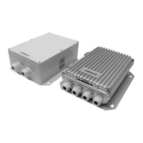
V1691 Series
Outdoor/Indoor Receiver/Drivers
Installation/Operation Instructions
This manual applies to below series products:
V1691/V1691X/V1691-24A/V1691E/
V1691EX/V1691E-24A
This manual describes the installation and operation procedures for V1691 Series Receiver/drivers. Compatible
with all Infinova series matrix switching systems, V1691 Series Receiver/drivers are designed to perform PTZ,
lens zoom in/out, focus, iris, and auxiliary functions at a camera site. A unique camera ID is assigned to each
receiver/driver, so the operators could only control the selected camera through the corresponding receiver/driver.
V1691 Series Receiver/drivers are classified as a single-channel type since one unit controls only one camera at a
site.
Advertisement
Table of Contents

Related Manuals for Infinova V1691 Series

Summary of Contents for Infinova V1691 Series
- Page 1 A unique camera ID is assigned to each receiver/driver, so the operators could only control the selected camera through the corresponding receiver/driver. V1691 Series Receiver/drivers are classified as a single-channel type since one unit controls only one camera at a site.
-
Page 3: Copyright Statement
This device must accept any interference received, including interference that may cause undesired operation. V1691 Series Receiver/drivers have been tested and found to comply with the limits for Class A digital device, pursuant to Part 15 of the FCC rules. These limits are designed to provide reasonable protection against harmful interference when the equipment is operated in a residential environment. - Page 4 Read this manual carefully before installation. This manual should be saved for future use. Important Safety Instructions and Warnings Electronic devices must be kept away from water, fire or high magnetic radiation. Clean with a dry cloth. Provide adequate ventilation. Unplug the power supply when the device is not to be used for an extended period of time.
-
Page 5: Table Of Contents
Appendix III Specifications ............10 3.1 System Connections ..............2 Appendix IV Typical System Connections ....... 11 3.1.1 Code Source to V1691 Series receiver/drivers ....2 1. Connect V2011 to V1691 ............11 3.1.2 Pan/Tilt and Lens Connections ........3 2. -
Page 7: Chapter I General Description
Chapter I General Description 1.3 Features 1.1 Description Single channel receiver/driver V1691 series receiver/drivers are designed as the remote control Flexible Pan/Tilt and Lens Control devices for operation of motorized camera pan/tilt units and 24VAC and 14VDC output motorized camera lens units. Since the camera sites are usually far AUTOPAN function away from the operators’... -
Page 8: Chapter Ii Installation
Unless specially noted, the descriptions Note: Take V1691 as an example to show unit installation in this illustrated for V1691 apply to all V1691 series receiver/drivers. chapter. Unless specially noted, the descriptions illustrated for V1691 apply to all V1691 series receiver/drivers. -
Page 9: Pan/Tilt And Lens Connections
3.1.2 Pan/Tilt and Lens Connections The connection to a Pan/Tilt unit and a motorized camera lens is Receiver B R+ W R- with a 12-pin connector. This connector, labeled J300, J301 is 120 - Ohm Terminator located on the main PCB (see Appendix II). A mating 12-position screw-terminal connector plug is provided. -
Page 10: Dip Switch Sw201
Figure 3-5 Manchester Mode PELCO-P SAMSUNG J204 Edge INFINOVA J201 Note: When selecting Manchester communication protocol set “OFF” for all positions of the DIP switch; When selecting Figure 3-6 RS-485 Mode PELCO-D communication protocol, the baud rate could be fixedly 2400bps. -
Page 11: Presets
Baud rate (bps) Protocol V2116 V2116+V2011 V2116 V2116+V2011 V2116 V2116+V2011 Manchester 1--64 1-72 1-72 Pelco P 1--255 1200--19200 2400--9600 1-64 1-64 Pelco D 1--255 1--32 1200--19200 2400 1-64 1-32 Infinova 1--128 1200--19200 2400--19200 1-64 1-60 Samsung 1--254 1200--19200 4800--38400 1-64 1-64... -
Page 12: Chapter Iv Operation
4.2 Powering On V1691 series receiver/drivers provides a pendant cord for use with a standard electrical outlet. For the power source required, please refer to Section 1.2 Models. The Receiver circuitry includes two transformers: one for the on-board circuitry, which has a non-replaceable thermal fuse;... - Page 13 1=ON, 0=OFF...
- Page 14 1=ON, 0=OFF The CAM address ranges from 1 to 255 for PELCO-P/D, from 1 to 128 for Infinova protocol, from 1 to 254 for SAMSUNG, and from 1 to 64 for Manchester protocol.
-
Page 15: Appendix Ii System Testing
Appendix II System Testing SW200 DIP Switch Function × × × × × × × × Down × × × × Left × × × × Right × × × × Left-up × × × × Left-down × × × ×... -
Page 16: Appendix Iii Specifications
(381 mm×165 mm×286 mm) Address Range: 1-255 Unit Weight Control Code: Manchester, RS485(SAMSUNG, V1691: 4.4 lbs. (2 kg) PELCO-P/D ,INFINOVA) V1691E: 6.6 lbs. (3 kg) Balanced, 120 Ω, shielded twisted pair Code Impedance: Shipping Weight Local Control: All functions V1691: 7.4 lbs. -
Page 17: Appendix Iv Typical System Connections
9 10 11 12 13 14 15 16 NONCCM NONCCM MONITORS RS232 PORTS ETHERNET MANCHESTER CODE RS485 PORT T+ T- GND B W S B W S B W S B W S V2011 J202 B R+ W R- V1691 Apply to all V1691 series receiver/drivers. -
Page 18: Connect V2015 To V1691
W S B W S B W S B W S RS485 RELAYS T+ T- GND NO NC CM NO NC CM PROG MON DATA LINE RS232 PORTS ETHERNET POWER VIDEO OUTPUTS V2015 J202 B R+ W R- V1691 Apply to all V1691 series receiver/drivers. -
Page 19: Connect V2020 To V2411-485 And V1691
T+ T- G T+ T- G T+ T- G T+ T- G T+ T- G T+ T- G T+ T- G T+ T- G T+ T- G T+ T- G T+ T- G T+ T- G V2411-485 J202 B R+ W R- V1691 Apply to all V1691 series receiver/drivers. -
Page 20: Connect V2116 Keyboard To V1691
NEXT HOLD CLOSE OPEN ETHERNET RS232 T+ T- G B W S ARM SALVO FOCUS Communication ports on V2116 rear panel NEAR PATRN SHOT PROG ZOOM OPERATE CLEAR WIDE TELE PROGRAM DOWN MENU V2116 Apply to all V1691 series receiver/drivers. -
Page 21: Connect Pan/Tilt & Lens To V1691
VACCOM LENSCOM ZOOM DOWN FOCUS VACCOM Camera IRIS 24VAC J300 J301 Apply to all V1691 series receiver/drivers. 6. Connect the camera & Pan/Tilt to V1691(with presets) Pan/Tilt AUX2 A ZOOMPOT AUX2 B FOCUSPOT AUX1 N/O TILTPOT AUX1 N/C PANPOT AUX1 COM... - Page 22 Infinova 51 Stouts Lane, Monmouth Junction, NJ 08852, U.S.A. Tel: 1-888-685-2002 (USA only) 1-732-355-9100 Fax: 1-732-355-9101 sales@infinova.com V2.1 0808...
Need help?
Do you have a question about the V1691 Series and is the answer not in the manual?
Questions and answers