Table of Contents
Advertisement
Quick Links
Advertisement
Table of Contents

Summary of Contents for Winbook N7405JV
- Page 1 N7405JV INSTRUCTION MANUAL IP CAMERA...
-
Page 2: Table Of Contents
Index INTRODUCTION........................ 1 ....................1 HE PACKAGE INCLUDES ..................... 1 UNCTION AND EATURES ..................... 2 UNCTION AND EATURES APPEARANCE AND INTERFACE..................3 ....................... 3 PPEARANCE ....................3 QUIPMENT INTERFACE CONNECT TO IP CAMERA OVER A LAN ............... 4 ......................4 AN CONNECTION ............ - Page 3 5.4.2 Time Setting......................16 5.4.3 Firmware upgrade....................16 5.4.4 Restore Factory Default..................17 5.4.5 User browsing Log....................17 CENTRALIZATION CONTROL..................17 FAQ..........................18...
-
Page 4: Introduction
1 Introduction The IP Camera combines a high quality digital video camera with network connectivity and a powerful web server to bring clear video to your desktop from anywhere on your local network or over the Internet. 1.1 The package includes IP Camera * 1 ... -
Page 5: Features
1.3 Function and Features Image Minimum Capture IR on,0 Lux illumination Lens f=3.6mm, F=2.0, Fixed Iris Lighting 12 850nm Infrared LEDs, 5m range Assistant Resolution 640*480(VGA)/320*240(QVGA)/160*120(QQVGA) Video and Audio r r i p i l TCP/IP、UDP/IP、HTTP、SMTP、FTP、DHCP、 Basic Protocols DDNS、UPNP、NTP、PPPOE Network Triggered Actions Email/FTP/ send message to alarm server Other... -
Page 6: Appearance And Interface
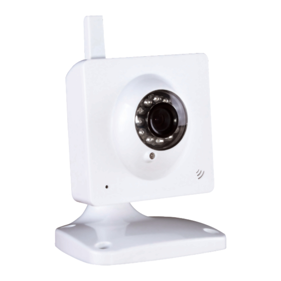
2 Appearance and Interface 2.1 Appearance Figure 1 Status Indicator: when device is running, flashes one or twice per second to indicate the wired network is connected; rapid flashing(2~3 times per second, indicates wireless network is connected. 2.2 Equipment interface Figure 2 - 3 -... -
Page 7: Connect To Ip Camera Over A Lan
3 Connect to IP Camera Over a LAN 3.1 Lan connection Figure 3 3.2 Search and set the IP address of the IP camera Run “BSearch_en.exe” from the support CD, the setting interface is as figure 4. Figure 4 Operation Steps: Click “Search (F3) Choose the device Change the IP address of the IP camera according to the information in the red frame... -
Page 8: View Ip Camera Video Feed
Put the user name and password into “Authentication” (By default, the user name is: admin, password is: 123456). Click “Update” After successfully updating, click “Search (F3)”, choose the device and click “Browse (F4)”. Then you may view the IP camera, as shown in Figure 5. NOTE: If you don’t know how to manually configure “IP config”, you can also tick the “Set IP automatically”... -
Page 9: Video Display
Figure 6 3.3.1 Video Display After installing the software, click the “Mode 1 to view” link as in Figure 5 to view the camera video feed (see Figure 7). Figure 7 Main Menu The main menu includes the function settings of the submenus Status Display The status display is in upper right corner, it shows the status of up to 9 devices: - 6 -... -
Page 10: Connect To Ip Camera Over A Wan
if not connected, button is gray if connected, button is green If wrongly connected, button is yellow If alarm, button is red Multi Device display area If User adds multiple devices (refer to section 5.3.2) , when shifting to 4-Ch or 9-CH, it will automatically show additional devices. -
Page 11: Port Forwarding
Port forwarding To view an IP Camera’s video feed from a WAN, you must enable port forwarding on the router the camera connects to. Using a Netgear router as an example: Figure 10 Setting Procedure: After logging in to the router interface,choose “Port Forwarding” Choose “Add custom Service”... -
Page 12: Third Party Ddns
Figure 11 4.3.2 Third Party DDNS User can also use a third part DDNS service, such as www.dyndns.com. User must apply for a free domain name from this website, enter the information for it and save the settings (see Figure 12). The domain name can then be used. Figure 12 Note: Using a third party domain name, if the http port is not 80, the port number must be added to the domain name following a colon. -
Page 13: Adsl Setting
Wireless Network List box. Select one of them and tick “Using Wireless Lan”, then the relevant data of the selected wireless network will be shown in the adjacent fields. Enter the “Share Key” access password and click “Set”, the WiFi access configuration is now complete. -
Page 14: Ddns Setting
Figure 16 Before using the UPNP function, please make sure the router’s UPNP function has been initialized. Not all routers support UPNP completely. Please test if the router works well with the camera equipment, if not, we suggest you disable this function and configure port-forwarding manually. - Page 15 Figure 18 User can select motion detection. If there is any motion, it will detect the motion and trigger an alarm. In Motion Detect Sensitivity, the larger the number selected, the more sensitive the motion detection. Note: For this model there are no Alarm I/O functions. 2)...
-
Page 16: Mail Service Setting
5.2.2 Mail Service Setting The camera will send an alarm email to you. You only need to fill in your email address as shown in Figure 20. After the entering the settings, click Save and Test to confirm it is working properly. -
Page 17: Alarm Server
In alarm mode, the camera will take a still image and send it to an FTP server. Please make sure your FTP settings are correct. See Figure 21 for reference. When all the information has been entered, click “Test” to see if the settings work. After configuring an FTP server, you can use the “Upload Image Periodically”... -
Page 18: Multi Device Setting
5.3.2 Multi Device Setting Figure 24 As Figure 24, User can add a maximum of 9 devices to view simultaneously. Click the Refresh button to check the device on the LAN. When you click a device, a configuration dialogue box will pop up. Enter the device info, as in Figure 25 and click Save. After that, you must also click Submit to save. -
Page 19: Maintain
5.4 Maintain 5.4.1 Device Information Figure 26 5.4.2 Time Setting If the camera device is connected to the Internet, you can enable the NTP server to adjust the time and select the right time zone. Or you should use the PC’s time setting to adjust the camera’s time setting. -
Page 20: Restore Factory Default
5.4.4 Restore Factory Default Click “Restore Factory Default”, it will pop up a dialogue box to confirm if you really want to restore the factory defaults. After confirmation, the system will restore the factory defaults and reboot. 5.4.5 User browsing Log After enter the log interface, you can view by whom and when the device is visited. -
Page 21: Faq
7 FAQ Incorrect power adapter will damage the equipment or power adapter When connecting a power adapter, please check the voltage carefully, it should be a 5V adapter for this equipment. Slowly browse speed This equipment uses an MJEPG compression format, it needs a lot of network bandwidth, less bandwidth will affect browsing speed. - Page 22 Figure 31 - 19 -...
Need help?
Do you have a question about the N7405JV and is the answer not in the manual?
Questions and answers