Table of Contents
Advertisement
Quick Links
- 1 Preparing Ceiling, Installing Hanger Bracket and Making Hanger Bracket Electrical Connections
- 2 Setting Accessory Remote Control Codes
- 3 Installing Accessory Remote Control Receiver and Making Remote Control Receiver Electrical Connections
- 4 Operating Your Sycamore Fan
- 5 Trouble Shooting
- 6 Technical Specifications
- Download this manual
Advertisement
Table of Contents

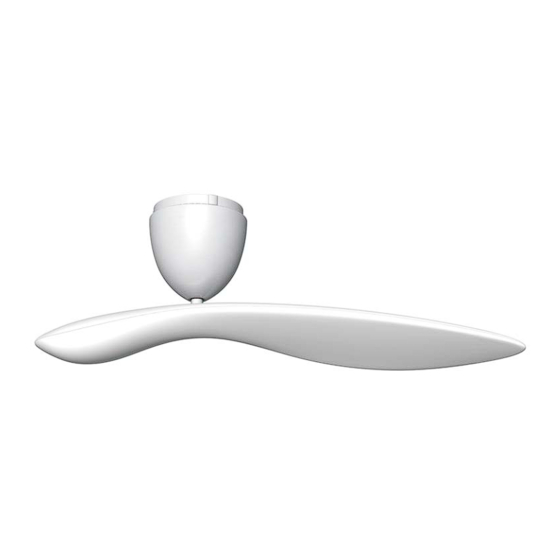
Summary of Contents for Sycamore Ceiling fan
- Page 1 Sycamore Ceiling Fan nature + technology Instruction Manual I N S T A L L A T I O N O P E R A T I O N M A I N T E N A N C E...
-
Page 2: Table Of Contents
Page 2 Unpacking Your Sycamore Fan ........ -
Page 3: Introduction
Introduction Thank you for choosing a Sycamore™ Ceiling Fan. You have chosen the best! We are confident that your new ceiling fan will provide many years of service and enjoyment. GENERAL PRECAUTIONS Please read and follow these instructions carefully, and be mindful of all warnings shown throughout this manual. -
Page 4: Important Safety Precautions
Important Safety Precautions LOCATION AND INSTALLATION REQUIREMENTS FOR YOUR FAN To provide adequate clearance from the floor the lowest point on the fan blade must be at least 2.1m (7’) from the floor. Note: For a fan mounted directly to the ceiling, the lowest point of the fan blade is approximately 365mm (14 ½”) below the ceiling. - Page 5 Important Safety Precautions ELECTRICAL ISSUES The fan and hanger bracket must be earthed. Do not attempt to control the operation of this fan from any wall controller that is not approved by Hunter Pacific International Pty Limited for use with this fan. DO NOT use a solid state wall controller.
-
Page 6: Unpacking Your Sycamore Fan
Unpacking your Sycamore Fan Unpack your fan and check the contents. You should have two cartons - a Motor Carton and a Blade Carton. Do not discard the cartons. If warranty replacement or repair is ever necessary, the fan should be returned in the original packaging. - Page 7 Unpacking your Sycamore Fan Remote Control (Accessory) Wall Controller Speed Controller Remote Control Receiver x 1 unit x 1 unit Rotary Speed Switch x 1 unit Remote Control Transmitter x 1 unit Capacitor x 1 unit Clip Battery x 1 unit...
-
Page 8: Preparing Ceiling, Installing Hanger Bracket And Making Hanger Bracket Electrical Connections
Checking Ceiling Condition and Preparing for Fan Installation Before commencing installation, turn off electricity supply at the main power box. Disconnect power by removing fuse or turning off circuit breaker before commencing work. Installation using Ceiling Mounting Box Installation directly mounted to Ceiling Joist Ceiling Joist behind ceiling Ceiling... - Page 9 Attaching Hanger Bracket to Ceiling using an Embedded Mounting Box Embedded Mounting Box Hanger Bracket Secure Hanger Bracket to Mounting Box using screws and washers provided. Ensure screws are securely tightened. Note: The Hanger Bracket can be securely screwed to a Mounting Box embedded in concrete or other load bearing material.
- Page 10 Attaching Hanger Bracket directly to Ceiling Drill holes in Ceiling Joist at approximately 90mm (3 ½”) centres for Hanger Bracket Ceiling Joist behind mounting. Power Drill Hanger Bracket Secure Hanger Bracket to Ceiling Joist using screws and washers provided. Ensure screws are securely tightened.
- Page 11 Connecting Live, Neutral and Earth Wires from Supply Wiring to Terminal Block on Hanger Bracket NEUTRAL SWITCHED LIVE Terminal Block from Wall Controller EARTH Ensure that electrical connections Make NEUTRAL and EARTH connections from incoming Mains are good and that terminal block supply to NEUTRAL and EARTH terminals on Hanger Bracket as screws are secure.
-
Page 12: Preparing And Installing Fan Motor Assembly And Making Fan Motor Assembly Electrical Connections
Preparing Fan Motor Assembly If installing a fan with a Suspension Rod, refer to Additional Instruction Manual for Suspended Installation for remaining installation steps. Suspension Ball Check that the Suspension Ball fixing screw is securely tightened. Fan Motor Housing Fixing Screw 6 - 8mm (1/4”... - Page 13 Installing Fan Motor Assembly into Hanger Bracket Position Fan Motor Assembly so that Chassis arm with terminal block is facing away from opening in Hanger Bracket. Locate Suspension Ball in Hanger Bracket. Ensure that lug on Hanger Bracket is engaged in slot in Suspension Ball.
- Page 14 Connecting Earth Wire from Fan Motor Assembly to Hanger Bracket EARTH (Green / Yellow) Make EARTH (Green/Yellow) connection from Fan Motor Assembly to appropriate terminal on Hanger Bracket. Ensure electrical connections are good, and that terminal block screws are secure. IF THERE ARE ANY PROBLEMS DURING INSTALLATION OF THE FAN, THE INSTALLER MUST CONTACT THE HUNTER PACIFIC INTERNATIONAL WARRANTY LINE BEFORE LEAVING THE WORK SITE...
- Page 15 Connecting Live and Neutral Wires from Fan Motor Assembly to Hanger Bracket - Wall Controller If you are using a Remote Control, skip this step and go to page 18. NEUTRAL (Blue) LIVE (Brown) Make LIVE (Brown) and NEUTRAL (Blue) connections from Fan Motor Assembly to appropriate terminals on Hanger Bracket using pre- installed wires on right side of Chassis terminal...
-
Page 16: Installing Wall Controller
Installing Wall Controller Warning: Do not attempt to control the operation of this fan from any wall controller that is not approved by Hunter Pacific International Pty. Limited for use with this fan. Do not use a solid state wall controller. The use of an unapproved wall controller voids the warranty. ON/OFF Switch Capacitor Double Sided Tape... - Page 17 Connecting Wires for Wall Controller Warning: Do not attempt to control the operation of this fan from any wall controller that is not approved by Hunter Pacific International Pty. Limited for use with this fan. Do not use a solid state wall controller.
- Page 18 Installing Front Plate and Rotary Speed Switch Front Plate Rotary Speed Switch Back Plate Fix pre-wired Wall Controller Back Plate to wall, clip on Front Plate, and press on Rotary Speed Switch. IF THERE ARE ANY PROBLEMS DURING INSTALLATION OF THE FAN, THE INSTALLER MUST CONTACT THE HUNTER PACIFIC INTERNATIONAL WARRANTY LINE BEFORE LEAVING THE WORK SITE .
-
Page 19: Wall Controller Installation Wiring Diagram
Wall Controller Installation Wiring Diagram Wall Controller Wall Plate LIVE (Active) from Mains Supply ON / OFF Switch NEUTRAL to Wall Switch not required Loop but may be present in some existing installations. NEUTRAL from Main Supply EARTH Conductor Rotary Speed Switch H a n g e r B r a c k e t Terminal Blocks... -
Page 20: Setting Accessory Remote Control Codes
Setting Code Switches for Remote Control Handset and Installing Battery If you are using a Wall Controller, skip these steps and go to Page 26. Check Remote Control Transmitter (Handset) CODE switch settings are identical to Receiver CODE switch settings (use point of ball point pen to adjust switches). - Page 21 Setting Code Switches for Remote Control Receiver Light wire (White) Check Remote Control Receiver CODE switch settings and adjust if required (use point of ball point pen to adjust switches). Terminate Remote Control Receiver light wire (marked Remote Control LIGHT OUT) using good Receiver quality electrical insulation tape as shown.
- Page 22 Code Settings for Remote Control Handset and Receiver Setting Handset and Receiver Codes if using one Remote Control Handset to control multiple fans Setting Handset and Receiver Codes if using individual Remote Control Handsets for each fan Note: Ensure that the maximum distance from the Remote Control Handset to Receiver does not exceed the range of the transmitter.
-
Page 23: Installing Accessory Remote Control Receiver And Making Remote Control Receiver Electrical Connections
Installing Remote Control Receiver in Hanger Bracket Aerial Tilt Fan Motor Assembly as shown and After installing Remote slide Remote Control Receiver into Control Receiver re- Fix Remote Control Receiver Aerial Hanger Bracket in orientation shown a d j u s t F a n M o t o r to ceiling within circle of Fan Motor (Code switches to be passed through Assembly to ensure... - Page 24 Removing pre-installed Live and Neutral Wires from Fan Motor Assembly Remove pre-installed LIVE (Brown) and NEUTRAL (Blue) wires from right side of terminal block on Fan Motor Assembly. IF THERE ARE ANY PROBLEMS DURING INSTALLATION OF THE FAN, THE INSTALLER MUST CONTACT THE HUNTER PACIFIC INTERNATIONAL WARRANTY LINE BEFORE LEAVING THE WORK SITE .
- Page 25 Connecting Live and Neutral Wires from Remote Control Receiver to Hanger Bracket NEUTRAL (Blue) LIVE (Brown) Make LIVE and NEUTRAL connections from Remote Control Receiver to appropriate terminals on Hanger Bracket using wires marked LIVE IN (Brown) and NEUTRAL IN (Blue). Ensure that electrical connections are good, and terminal block screws are secure.
- Page 26 Connecting Live and Neutral Wires from Remote Control Receiver to Fan Motor Assembly NEUTRAL (Blue) LIVE (Brown) Make LIVE and NEUTRAL connections from Remote Control Receiver to appropriate terminals on Fan Motor Chassis using wires marked L (Brown) and N (Blue). Ensure Remote Control Receiver LIGHT Wire is well secured and cannot touch any moving parts.
-
Page 27: Accessory Remote Control Installation Diagram
Remote Control (Accessory) Installation Wiring Diagram AC IN (Blue) NEUTRAL from Mains Supply AC IN (Brown) SWITCHED LIVE (Active) from Wall Switch Hanger Bracket Remote Terminal Control Hanger Blocks Bracket Receiver Earth EARTH Conductor E (Green/Yellow) Note: As shown, the Remote Control Receiver is wired in series between the Hanger Bracket terminal and the Chassis terminal. -
Page 28: Preparing And Installing Fan Motor Housing
Preparing Fan Motor Housing Fan Motor Housing Fan Motor Housing Screw Cover Ensure Fan Motor Housing Screw Covers are in fully open position. IF THERE ARE ANY PROBLEMS DURING INSTALLATION OF THE FAN, THE INSTALLER MUST CONTACT THE HUNTER PACIFIC INTERNATIONAL WARRANTY LINE BEFORE LEAVING THE WORK SITE . - Page 29 Attaching Fan Motor Housing to Fan Motor Assembly Ensure that Fan Motor Housing fixing point with hole (not bayonet slot) is aligned with Chassis arm from which fixing screw was removed (see page 10). Install Fan Motor Housing using a clockwise bayonet action. Line up fixing hole in Fan Motor Housing with screw hole in Chassis arm and install fixing screw removed on page 10.
- Page 30 Closing Screw Covers Close all three Screw Covers. Note: To remove Fan Motor Housing open Screw Covers using a flat bladed screw driver as shown. Remove fixing screw from hole, loosen two bayonet slot screws and remove Fan Motor Housing by rotating anticlockwise and lowering.
-
Page 31: Preparing And Installing Fan Blade
Preparing Fan Blade for Installation Pivot Connector Rotate Fan Blade Screw Cover to expose fixing hole in Pivot Connector as shown. IF THERE ARE ANY PROBLEMS DURING INSTALLATION OF THE FAN, THE INSTALLER MUST CONTACT THE HUNTER PACIFIC INTERNATIONAL WARRANTY LINE BEFORE LEAVING THE WORK SITE . - Page 32 Attaching Fan Blade to Fan Motor Assembly Drive Shaft Pivot Connector Align flats on Pivot Connector with flats on Drive Shaft and install Fan Blade by sliding Pivot Connector onto Drive Shaft. Hold Fan Blade in position, Take care not to lift Drive Shaft when installing Fan Blade, as insert blade fixing screw and this may disengage Suspension Ball from lug on Hanger tighten securely.
- Page 33 Closing Screw Cover on Pivot Connector Rotate Screw Cover to hide screw head. (Note: Rotating the Screw Cover will prevent blade fixing screw from falling out should it become loose.) IF THERE ARE ANY PROBLEMS DURING INSTALLATION OF THE FAN, THE INSTALLER MUST CONTACT THE HUNTER PACIFIC INTERNATIONAL WARRANTY LINE BEFORE LEAVING THE WORK SITE .
- Page 34 Installation Check Ceiling Rotate Fan Blade by hand to ensure it does not hit anything. Make sure that the Drive Shaft is vertical, and that the gap between the Fan Motor Housing and ceiling is even. If the Drive Shaft is not vertical, the fan may wobble. Once the installation is completed and has been checked, the electricity supply can be turned on at the main power box.
-
Page 35: Operating Your Sycamore Fan
Operating your Sycamore Fan - Wall Controller To operate your fan using a Wall Controller turn the ON/OFF Switch to the ON position, then ON/OFF Switch turn the Rotary Speed Switch to the desired speed setting: 0 - Off I - High speed II - Medium speed III - Low speed. - Page 36 To change between speeds, press the button for the new speed. There is no need to stop the fan when changing speed. The LIGHT button has no function on the Sycamore fan. If the Remote Control Handset for your fan has an LCD display, refer to the diagram below for an explanation of the symbols displayed on the LCD screen.
-
Page 37: Care And Cleaning
When cleaning your fan, only use a soft brush or lint free cloth to avoid scratching the finish. DO NOT use water when cleaning your ceiling fan. It could damage the motor or the blade and/or create the possibility of electric shock. -
Page 38: Trouble Shooting
These signals may cause an intermittent humming in the ceiling fan. Filters are available in Australia at customer cost. It is not the fault of the ceiling fan. If the fan rotates but does not create much airflow. -
Page 39: General Information On Ceiling Fans
Movement of a couple of centimetres is quite OK and does not suggest that the fan will fall down. The Sycamore fan is mounted securely on a metal Hanger Bracket with rubber cushioning and a ball joint to allow free movement. -
Page 40: Technical Specifications
Technical Specifications Suspended Version (Accessory) 170 mm 210 mm Standard Suspension Kit suitable for raked ceilings up to 22 . 45 Kit also available. 1000 mm Colour Operating Speeds (Approximate figures at 230 - 240v AC) Motor Housing: Black / White / Brushed Aluminium Low: 80 rpm Blade:... -
Page 41: Warranty
Ceiling Fan Warranty Period. The ceiling fan itself, excluding accessories such as the Remote Control Transmitter and Receiver, is covered by a 2 year in-home warranty. During this period, Hunter Pacific International Pty. Limited will, at its discretion, repair or replace defective product. - Page 42 Sycamore Ceiling Fans not purchased and installed in Australia. A service call fee will be charged where; there is nothing wrong with the ceiling fan or; the defective operation of the ceiling fan is due to failure of electricity or; the installation is not in accordance with Hunter Pacific International Pty.
- Page 43 Please Note: When phoning for warranty you will require the following information; date of purchase; retailer from whom the fan was purchased; model and colour of the fan. The installing electricians details may also be required. SYCAMORE CEILING FAN WARRANTY DETAILS Please File with your Purchase Receipt Customer Details...
- Page 44 All rights reserved. No part of this publication may be reproduced in any form or by any means without the prior written permission of Sycamore Technology. Copyright © 2006 Sycamore Technology, Sydney, Australia Sycamore is a registered trademark of Sycamore Technology.
Need help?
Do you have a question about the Ceiling fan and is the answer not in the manual?
Questions and answers