Table of Contents
Advertisement
Advertisement
Table of Contents
Troubleshooting

Related Manuals for eddyfi Ectane 2

Summary of Contents for eddyfi Ectane 2
- Page 1 User’s Guide...
-
Page 2: Battery Charger Precautions
The Ectane 2 should only be used by qualified personnel. When carrying the Ectane 2, it is the user’s responsibility to make sure that the safety precautions used are in accordance with the local department of transportation’s (or equivalent governing body) rules and regulations. -
Page 3: Marking And Symbols
Electronic Equipment (commonly known as WEEE) should never be disposed of in the public waste stream. Calibration and Warranty Seals Calibration and warranty seals are hidden under the Ectane 2’s front-left bumper to prevent accidental damages. Important Broken seals void the calibration certification and product warranty. -
Page 4: Safety Indications
Safety Indications The purpose of the various safety indications in this manual are meant to ensure operator safety and instrument integrity. WARNING! The Warning sign indicates a hazard. It calls attention to a procedure, practice, or the like, which, if not correctly performed or adhered to, can result in personal injury. -
Page 5: Typographical Conventions
Typographical Conventions The various typographical conventions used in this document are explained below and were designed to standardize and simplify the look and feel of this document. Italic An italic typeface is used to indicate emphasis on a specific word or phrase (i.e., This options should never be selected.) Bold... -
Page 6: Table Of Contents
Calibration and Warranty Seals ..................... iv Safety Indications .......................... v Typographical Conventions ......................vi Table of Contents ......................... vii Introducing the Ectane 2 ............1 Presentation ..........................2 What is in the Box ........................2 Instrument Description ......................3 Ground Connector .......................... 8 Battery Compartment ........................ -
Page 7: Table Of Contents
viii IRIS Connector ..........................36 Connectors ....................36 URRENT RRAY Ethernet Connector ........................37 Specifications ................ 39 General ............................40 System ..........................40 Power Requirements ......................40 Environmental Conditions ...................... 41 Housing ..........................41 Ethernet Cable ........................41 Motor Drive for Rotating Probes ..................... 42 Current Source for Saturation Probes .................. -
Page 8: Introducing The Ectane 2
Introducing the Ectane 2... -
Page 9: Presentation
Battery power and backup for flexibility and 100 % uptime Plug-and-play connectivity — no more BootP Standard connectors ® The Ectane 2 is controlled by a computer running Microsoft Windows XP or ® ® Windows 7 and Eddyfi’s Magnifi... -
Page 10: Instrument Description
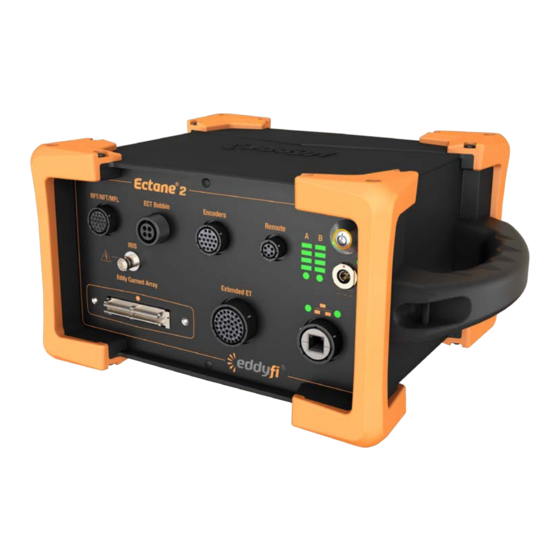
Instrument Description At this time, the Ectane 2 is available in 11 different configurations. Numbers after the model’s name indicate the maximum number of available channels with this instrument. The RNM option indicates RFT, NFT, and MFL capabilities. The I option indicates IRIS capabilities. - Page 11 Figure 1 Ectane 2 E Figure 2 Ectane 2 E64 and E128 Chapter 1: Introducing the Ectane 2 Presentation...
- Page 12 Figure 3 Ectane 2 E256 Figure 4 Ectane 2 I Presentation...
- Page 13 Figure 5 Ectane 2 ERNM Figure 6 Ectane 2 ERNMI Chapter 1: Introducing the Ectane 2 Presentation...
- Page 14 Figure 7 Ectane 2 E64RNM and E128RNM Figure 8 Ectane 2 E64RNMI and E128RNMI Presentation...
-
Page 15: Ground Connector
Ground Connector Behind the instrument, you will find the ground connector used to ground the Ectane 2 when the situation requires it. Figure 9 Ground connector The ground connector is a simple screw that you remove to insert the ground wire, putting the screw back in to secure the connection. -
Page 16: Battery Compartment
Battery Compartment The Ectane 2 can be powered by an external AC/DC supply or by two, high-power batteries. The batteries are accessible from a side access panel, as shown below. Figure 10 Battery compartment Firmware backup button Important The firmware backup button is used in cases where the Ectane 2’s original firmware becomes corrupted. -
Page 17: Preparing The Instrument
Preparing the Instrument... -
Page 18: Setting Up The Instrument
Never use the instrument when it is upside down (batteries on top). This position prevents the batteries from properly dissipating heat and can lead the Ectane 2 to enter its power safe mode. For details about the power safe mode, see “Environmental Conditions” on page 41. -
Page 19: Connection Configurations
Connection Configurations The Ectane 2 allows various test configurations. The following figures illustrate some of these configurations. ™ Figure 1 Typical configuration 1: Ectane 2 with SmartMUX probe Figure 2 Typical configuration 2: Ectane 2 with SmartMUX, scanner, and probe... - Page 20 Figure 3 Typical configuration 3: Ectane 2 with bobbin probe Chapter 2: Preparing the Instrument Setting Up the Instrument...
-
Page 21: Starting The Instrument
Ectane 2. Connect the power adapter to the power cord. Connect the power adapter to the power socket on the front of the Ectane 2. Connect the power cord to the power outlet. Press the power button until it clicks. -
Page 22: Battery Indicators
Figure 4 Power indicators Power button indicator External power indicator Battery Indicators Each battery has its own charge level indicator and charging status indicator. Figure 5 Battery B indicators Charge level indicators Charging status indicators Chapter 2: Preparing the Instrument Understanding Indicators... - Page 23 Figure 6 Battery corresponding to battery indicators Battery A Battery B Charge level indicators light and blink depending on each battery’s charge level, as explained below: LED 1 (from bottom) is blinking Charge is less than 10% LED 1 is solid Charge is over 10% LED 2 is solid Charge is over 25%...
- Page 24 Indicators are set off for up to 1 minute when the instrument in turned on. Note In the event that the Ectane 2 shuts down because of low battery power or Note overheating, the instrument automatically starts again once the shutdown condition clears.
-
Page 25: Connection Indicators
Connection Indicators Just above the Ethernet port, two indicators provide the state of the communications between the Ectane 2 and your workstation. Figure 7 Connection indicators Connection speed indicator Connection indicator The connection speed indicator can be in one of three states:... -
Page 26: Managing Batteries
Managing Batteries... -
Page 27: General
When carrying the Ectane 2, it is the user’s responsibility to make sure that the safety precautions used are in accordance with the local department of transportation’s (or equivalent governing body) rules and regulations. -
Page 28: Battery Charger Led Status Indicator
Figure 1 Battery charger Battery bays Calibration buttons Status window To charge the batteries with the optional, external charger: Place the charger on a flat and level surface, away from heat and moisture sources. Insert the power supply’s DC connector into the back of the external charger. Connect the power supply to an AC supply using the supplied cable. -
Page 29: Removing The Batteries
Removing the Batteries Normally, you can leave the batteries in the Ectane 2 as long as you want. However, there are times when you must remove them from Ectane 2 (e.g., for calibration purposes or before placing the instrument on a plane). -
Page 30: Hot-Swapping Batteries
Hot-Swapping Batteries You can remove the batteries in the Ectane 2 one at a time, when the instrument is turned on. Normally, the Ectane 2 can run on only one battery. Should the power left in the remaining battery be insufficient to keep the Ectane 2 running, the instrument will shut down without damaging electronic components. - Page 31 Indicators are set off for up to 1 minute when the instrument is turned on. Note In the event that the Ectane 2 shuts down because of low battery power or Note overheating, the instrument automatically starts again once the shutdown condition clears.
-
Page 32: Connector References
Connector References... -
Page 33: Extended Et Connector (41 Pins)
DC power supply. Description 41-pin, female, shell 20 connector Manufacturer, number Amphenol 58-570127-41S Eddyfi NDT, Inc., MACN4012 Suggested cable connector ITT Cannon, KPT06B20-41P Amphenol PT06J-20-41P Eddyfi NDT, Inc., MACN0005 Figure 1... - Page 34 Table 1 ET connector pinout (continued) XTENDED Signal Description N, P Outputs ECT2 Generator / 100 Ω ECT2 eddy current generator outputs through 100 Ω Output ECT2 Generator / 100 Ω ECT2 eddy current generator outputs through 100 Ω (if external MUX and motor encoder are not connected) Input Motor Rotation +...
- Page 35 Table 1 ET connector pinout (continued) XTENDED Signal Description Input In2 + input Positive input of input amplifier 2 Input In2 – input Negative input of input amplifier 2 Input In3 + input Positive input of input amplifier 3 Input In3 –...
-
Page 36: Rft/Nft/Mfl Connector (19 Pins)
RFT generator outputs, the RFT channel amplifier inputs, and a DC power supply. Description 19-pin, female, shell 14 connector Manufacturer, number Amphenol, 58-570124-19S Souriau 851-02E1419S50A7 Eddyfi NDT, Inc., MACN4015 Suggested cable connector ITT Cannon, KPT06A14-19P027 Amphenol PT06J-14-19P Eddyfi NDT, Inc., MACN4021 Figure 2 connector... - Page 37 Table 2 connector pinout (continued) Signal Description +15 V supply +15 V supply voltage, 1.0 A max. Output Drive2_OUT Coil driver #2 output – Ground Output Drive1_OUT Coil driver #1 output –15 V supply –15 V supply voltage, 1.0 A max. Input RFT_IN 2+...
-
Page 38: Ect Bobbin Connector (4 Pins)
4-pin inspection OBBIN probes. Description 4-pin, female, shell 14 connector Manufacturer, number Amphenol ACS02A-14S-2S (472) Eddyfi NDT, Inc., MACN4020 Suggested cable connector Amphenol 97-3106A-14S-2P Eddyfi NDT, Inc., MACN0059 Figure 3 ECT B connector OBBIN... - Page 39 Description 18-pin, female, shell 14 connector Manufacturer, number Amphenol 58-570124-18S Eddyfi NDT, Inc., MACN4014 Suggested cable connector ITT Cannon, KPT06B14-18P Amphenol PT06J-14-18P Eddyfi NDT, Inc., MACN0011 Figure 4...
-
Page 40: Encoders Connector (18 Pins)
Table 4 connector pinout (continued) NCODERS Signal Description Output Alarm Used to indicate that the probe is in the air (for tube inspections) (open drain with 10 kΩ pull-up). Relay contact Relay 2 Relay used for automatic acquisition sequence control Relay contact Relay 3 Relay used for automatic acquisition sequence control... -
Page 41: Iris Connector
E URRENT . These connectors are specific and designed by Eddyfi. RRAY For details about the Eddyfi 160-pin connectors, contact Eddyfi directly at info@eddyfi.com. Chapter 4: Connector References IRIS Connector... -
Page 42: Ethernet Connector
Bi_DC– Bidirectional pair C– Bidirectional Bi_DB– Bidirectional pair B– Bidirectional Bi_DD+ Bidirectional pair D+ Bidirectional Bi_DD– Bidirectional pair D– Important The Ectane 2 must be linked to a workstation with at least a category 5e, shielded, Ethernet cable. Ethernet Connector... -
Page 43: Specifications
Specifications... -
Page 44: General
Transfer rate on Ethernet cable 1 Gbps The warm-up time corresponds to the time required by the unit to reach its optimal accuracy after it is turned on. Eddyfi recommends waiting until the end of the warm-up period before balancing probes or performing acquisitions. -
Page 45: Environmental Conditions
RoHS ® The Ectane 2 warns you through Magnifi when its operating temperature reaches 65 °C ( 149°F), and then enters power safe mode to better protect itself when the operating temperature reaches 70 °C (158 °F). In power safe mode, some internal circuitry shuts down, acquisitions are stopped, and the instrument becomes inactive for work purposes until the condition that initiated the power safe mode is corrected. -
Page 46: Motor Drive For Rotating Probes
Motor Drive for Rotating Probes Voltage 0–24 V Maximum peak output current Maximum continuous output current Maximum continuous power 10 W Current Source for Saturation Probes Range 0–1 A Maximum output power 10 W Maximum output voltage 15 V Chapter 5: Specifications General... -
Page 47: Inspection Techniques
Inspection Techniques This section presents the Ectane 2’s operating specifications by inspection technique. Eddy Current Testing (ECT) Probe inputs Number of frequencies Frequency range 5 Hz – 10 MHz Generator s/ Coil drivers Generator output / Coil drive Up to 20 V, peak-to-peak... -
Page 48: Eddy Current Array (Eca)
Connector type Single or double, 160-pin connector The Ectane 2 uses an ID device found in Eddyfi probes. This ID device contains information that helps set up acquisitions and confirm compatibility between setup and probe. Remote/Near-Field Testing (RFT / NFT) -
Page 49: Magnetic Flux Leakage (Mfl)
Magnetic Flux Leakage (MFL) Probe inputs 4 on 19-pin RFT/NFT/MFL connector 8 on 41-pin E ET connector XTENDED Receiver gain 41 dB range, 23 – 64 dB Connector type 19-pin RFT/NFT/MFL connector 41-pin E ET connector XTENDED Internal Rotary Inspection System (IRIS) Number of UT channels 1, pulse-echo Transducer frequency... -
Page 50: Maintenance & Troubleshooting
Maintenance & Troubleshooting... -
Page 51: Preventive Maintenance
Due to its design, the Ectane 2 only requires minimal maintenance. Because it has no moving parts, the Ectane 2 also does not require any preventive maintenance by the user. Only a regular inspection of the instrument is recommended, to ensure that it is properly grounded. -
Page 52: Calibrating Batteries
CAUTION During calibration, the charger may become warm. Troubleshooting To trouble shoot the Ectane 2, you must first connect it to a workstation running ® Magnifi . Troubleshooting information is found in the Magnifi documentation. -
Page 53: Accessories
Accessories... -
Page 54: Protective Caps
Adapters and Connectors The Ectane 2 connectors were chosen to match the most common connectors in use today. You could, however, have specific needs outside the connectors supplied with the Ectane 2. Eddyfi offers a comprehensive array of adapters and specialty connectors to suit your needs. -
Page 55: Warranty, Trademarks, Copyrights
Warranty, Trademarks, Copyrights... -
Page 56: Limited Warranty
Limited Warranty Eddyfi NDT, Inc. warrants the hardware to be free of any defects in materials or workmanship for a period of twelve (12) months from the date of delivery, under normal use and service. These warranties are limited to the original purchase of the product and are not transferable. -
Page 57: Copyrights
Copyright Act of Canada, by laws of other countries, and by international treaties, therefore may not be reproduced, in whole or in part, whether for sale or not, without prior written consent from Eddyfi , Inc. Under copyright law, copying includes translation in other languages and formats. - Page 58 F + 1 418-780-2354 info@eddyfi.com www.eddyfi.com © Eddyfi NDT, Inc. Eddyfi, Ectane, Magnifi, and their associated logos are trademarks or registered trademarks of Eddyfi NDT, Inc. Eddyfi reserves itself the right to change product offerings and specifications without notice. 2013-08-11...