Table of Contents
Advertisement
Quick Links
Advertisement
Table of Contents

Subscribe to Our Youtube Channel
Summary of Contents for THOMSON SuperXpander LDK 4482
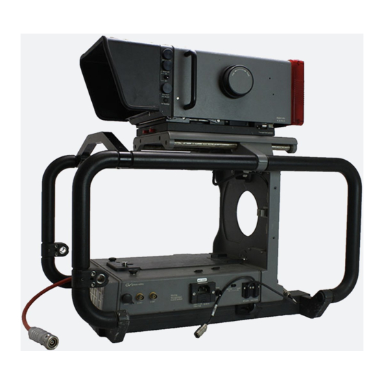
- Page 1 LDK 4482 LDK 4482 LDK 4482 LDK 4482 LDK 4482 SuperXpander 3922 496 48661 St.01...
-
Page 2: Declaration Of Conformity
Liable to technical droits sont réservés pour le cas de la alterations in the course of further délivrance d'un modèle d'utilité. Sous development. réserve de modification au cours de l'évolution technique. © Thomson Multimedia Broadcast Solutions 2002... -
Page 3: Table Of Contents
LDK 4482 SuperXpander User's Guide Contents Location of Controls and Functions ....1-2 Connections ............. 1-10 Location of Controls and Functions for HS ..1-4 Service Information .......... 1-14 02.38.3 User's Guide LDK 4482 - SuperXpander... -
Page 4: Location Of Controls And Functions
Location of Controls and Functions Rear Panel FILTER MSC. VIEWFINDER SIGN Camera on Centre Lamp 1(CLR) Ext 1 Remote cross Heater On air Safe Auto Select Ext 2 Dimm zone white Focus Y/ext Call Boost camera is in the local control mode. Optical filter selection Select the optical filter by touching the appropriate LED indicators... - Page 5 FILTER MSC. VIEWFINDER SIGN Camera on Centre Lamp 1(CLR) Ext 1 Remote cross Heater On air Safe Auto Select Ext 2 Dimm zone white Focus Y/ext Call Boost The Y or Y+c (contours added) signal is selected in Viewfinder indicators switch the Vf/Lens \ Vf Inst \ Vf mon menu on the camera.
-
Page 6: Location Of Controls And Functions For Hs
Location of Controls and Functions for HS Rear Panel FILTER MSC. VIEWFINDER SIGN Camera on Centre Lamp 1(CLR) Ext 1 Remote cross Heater On air Safe Auto Ext 2 Dimm zone white Focus Y/ext Call through frequently used menus, displayed in the Pip switch viewfinder screen. -
Page 7: Ldk 4482
Left Panel 70 VA max outlet could interrupt camera operation.) Triaxial cable connector Connects the large lens adapter to the base station Utility outlet power indicator and carries all signals and power. Lights when power is available at the utility outlet. Utility outlet fuse Script light connector This fuse protects the utility outlet. -
Page 8: Ldk 4482
Right Panel POWER WARNING THIS APPARATUS REMOTE LOCAL MUST BE EARTHED VF.2> >VF.1 >External 230V AC T1.6A 50-60 Hz VF (cam) LENS (cam) 115V AC T4A The frequency of the mains power supply must be Second viewer socket (VF2) between 47Hz and 63Hz. A 12-pole male socket for the connection of a second Mains power supply On/Off switch viewer. -
Page 9: Ldk 4482
Assembly Viewfinder Mount Retaining Knob Support Lens 70 VA max rail slot Locking Handle Lens support rail Balance Knob Bayonent Ring Locking Lever Mounting a Lens It is important that you assemble and disassemble the units in the right order. The correct order of assembly To mount the lens onto the large lens adapter, proceed is as follows: as follows:... -
Page 10: Ldk 4482
NOTE: Due to tolerances it is possible that the lens cannot be secured. Therefore there are two knurled Adjustment Camera screws on top of the Electronic screws attachment Unit with which the Camera block attachment block can be adjusted. Turn the screws clockwise to raise block turn counterclockwise to lower the... -
Page 11: Ldk 4482
Cable Clamp Rain and Off-use Cover When the lens and camera are mounted on the large The rain and off-use cover LDK6989/00 must be used lens adapter it is necessary to clamp the camera when the camera system is in wet or damp environment. cable. -
Page 12: Connections
Connections Connector Signals In each of the following figures the connectors are pins on the solder side of the connector. The part shown as seen on the panels of the camera. Remember numbers of the panel connectors can be found in the to use the mirror image of the drawings to identify the spare parts lists of the service manual. - Page 13 Monitor Connector (X608) 12-pin male 1. Housing 2. -80V 3. no connection 4. +13V 5. no connection 6. D-SCL 7. GND 8. D-SDA 9. D-INTN 10.Video 2 in 11.Video return 12.Video 1 in Shield of cable directly to the connector housing. Mains Supply Input Connector (X601) Eurostyle 3-pin male 1.
- Page 14 Lens Flying Lead Connector (X611) 12-pin male 1. no connection 2. no connection 3. GND (power ret.) 4. no connection 5. Iris control 6. no connection 7. Iris follow 8. Iris auto/remote 9. no connection 10.Zoom follow 11.Focus follow 12.Spare Shield of cable directly to the connector housing.
- Page 15 Lens Connector (X603) 36-pin female not used not used not used +12V GND (power return) GND (servo return) Housing R.E. A R.E. B R.E. C not used Iris F. (follow) Zoom F. (follow) Ext SW 1 Ext SW 2 not used Iris Iris A/R (auto/remote) Zoom...
-
Page 16: Service Information
Service Information When using the Large Lens Adaptor with older Viewfinders LDK4016/02 it is possible that a hum appears in the picture. Also no text display will be available. To solve these problems the following changes in the Viewfinder LDK4016/02 have to be performed.
Need help?
Do you have a question about the SuperXpander LDK 4482 and is the answer not in the manual?
Questions and answers