Table of Contents
Advertisement
Quick Links
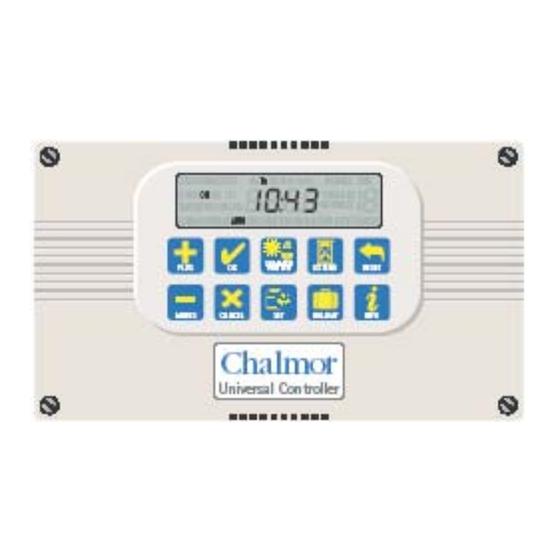
Autolux ~ Universal
Installation and User Manual
Increase a value.
Decrease a value.
Accept a newly entered value.
Cancel overtime, holiday,
edited value or current
submenu.
Apply British Summer Time or
Greenwich Mean Time.
Lighting
for UNI/L version
Quick Guide
Controller
Enter the settings menu.
Initiate or quickly extend a
time program.
Initiate a holiday period.
End overtime, holiday or reset
time logs in engineers menu.
Toggle the display between
time and sensor readings
Advertisement
Table of Contents

Summary of Contents for Autolux UNI/L version
- Page 1 Autolux ~ Universal Lighting Controller Installation and User Manual for UNI/L version Quick Guide Enter the settings menu. Increase a value. Initiate or quickly extend a Decrease a value. time program. Initiate a holiday period. Accept a newly entered value.
-
Page 2: Table Of Contents
Autolux ~ Universal Lighting Controller Installation and User Manual CONTENTS Introduction ................3 1 Technical Specifications .....…......….. 3 1.1 Operating Environment ..........….. 3 1.2 Performance Specifications .……………......3 1.3 Electrical Specifications …………………..…………..4 2 Installation Instructions ........……..5 2.1 Mounting the Control Assembly ....…………..5 2.2 General Wiring Specifications ......………………7... -
Page 3: Introduction
Autolux ~ Universal Lighting Controller Installation and User Manual INTRODUCTION This manual describes the Installation and Operation of the Autolux ~ Universal Lighting Controller This control must be installed according to the current IEE Wiring Regulations and should include full disconnection means and fusing appropriate to the connected loads. -
Page 4: Electrical Specifications
1.3 Electrical Specifications The power supply is SELV isolated, therefore all remote sensor and remote switch wiring to the control does not need to be mains level rated, but should be insulated to the highest voltage present where entering the control box. Relay 1 is rated Generally, it is recommended that 16A/240Vac resistive... -
Page 5: Installation Instructions
2 INSTALLATION INSTRUCTIONS 2.1 Mounting the Control Assembly Ensure that the controller is installed no less than 1.5m above the floor level. The controller should be positioned to allow the user easy access to the push buttons and to read the LCD display. The controller can be positioned with the cable entry to the bottom or the top depending on the cable routing. - Page 6 The housing consists of a two part plastic moulding held together by four screws. Plugs are supplied to cover the screws following installation. Knockouts are provided for cable glands to allow mains and remote sensor and switch cables to be fitted to the control assembly.
-
Page 7: General Wiring Specifications
2.2 General Wiring Specifications Connect as shown below. A suitably qualified person must make all wiring connections. Please refer to the following wiring connection drawings (see 2.3) and observe the notes referring to cable type and length. Failure to follow these guidelines may result in electrical interference or unsatisfactory operation. -
Page 8: Wiring Connections
2.3 WIRING CONNECTIONS External connections are by 27 screw terminals as follows: Screw terminals are 7.5mm and 5mm spacing rising clamp style with 2.5mm² wire entry size for power connections and with 1.5mm² wire entry size for signal connections. The terminal identification and description are provided below, together with the maximum terminal capacity in mm (shown in brackets). -
Page 9: Occupancy Sensor Wiring Connections
2.4 OCCUPANCY SENSOR WIRING CONNECTIONS – S1 to S6 Where occupancy detection is required, a range of BlueWave sensors are designed for use with the Universal Controller. The preferred cable is 4-core stranded and connections will be as follows: Universal Controller BlueWave Sensor ALM (ALARM) ALM (ALARM) -
Page 10: Remote Switch Wiring Connections
2.6 REMOTE SWITCH WIRING CONNECTIONS – S1 to S6 Where remote switches are to be connected, two switch options exist: a) Momentary push button / retractive switch / push switch Universal Controller Push switch PUSH TO BREAK (N/C) Note Where more than one push switch is required on an input, simply connect additional switches in series. -
Page 11: Operating Instructions
3 OPERATING INSTRUCTIONS 3.1 The buttons The ten buttons have the following functions: Enter the settings menu. Increase a value. Initiate or quickly extend a Decrease a value. time program. Initiate a holiday period. Accept a newly entered value. End overtime, holiday or Cancel overtime, holiday, reset time logs in engineers edited value or current... -
Page 12: The Display
3.2 The display During normal operation the time and day will be displayed. When the user is not programming or inspecting a parameter, the display will cycle through the status of each zone. The status shows the demand for each of the controlling elements, Timer (t), Lux (L), PIR / Push Switch (P) or Frost (F). -
Page 13: Setting User Parameters
3.4 Setting user parameters The controller can be set to operate in a variety of modes to suit the application. Press the SET button when in normal display mode allows the user to set various parameters within the unit. Repeat presses of SET cycle through the parameters to be set as follows. -
Page 14: Setting The Auto Mode
3.6 Setting the Auto Mode Auto Mode defines which controller or sensor inputs the zone will respond to when activating the zone relay. Auto Off means the zone will only respond to the panic override and frost settings. Auto Lux means that the zone will be controlled by light level sensors and/or PIR sensors, as assigned under the Engineers Menu. -
Page 15: Setting The Program (On / Off Times)
3.7 Setting the Program (on / off times) Each zone relay can be programmed to be active during certain times of the day. Two active periods can be programmed, between ON 1 and OFF 1 and between ON 2 and OFF 2. The second on/off period can be skipped if not required. -
Page 16: Setting The Lux Level
Two timeslots per day are allowed, where each timeslot includes an ON and OFF time. Once a day’s time program has been completed the day icon will flash for the next day. To finish with the program settings press cancel or reset after pressing OK for the last programmed day. -
Page 17: Setting The Extend Feature
3.10 Setting the Extend feature The EXTEND key can be used to initiate or extend a temporary override timer. When in Auto-Clock mode, this will When in Auto-Lux mode, this will override the clock programme on or override the occupancy or press off. -
Page 18: Setting Holiday
Press OK to initiate the extend period. The normal clock display will be replaced with an overtime countdown. While in extend mode the extend period can be increased or decreased by pressing the extend key. The time can be modified without having to reprogram the extend type or applicable zones. - Page 19 3.13 Battery Type & Replacement The real time clock and program information is battery backed up by a lithium coin cell. When mains power is interrupted, the clock, backed by the battery, will continue to operate normally for seven days after which it will stop. The battery will continue to back up the program information.
-
Page 20: Engineer Functions
4. Engineer Functions. The engineer functions allow you to program various advanced parameters. In order to access the engineer function press and hold the + button and press the SET button. The [SET] and[ENGINEER] icons are displayed. All control functions may be optionally password protected by a PIN code. Pressing the CANCEL button during programming will cause the setting being programmed to change back to its original value. -
Page 21: Programming The Engineering Functions
4.2 Programming the engineering functions All engineer functions are displayed as a code in the first two digits if the display, e.g. C1, t1, t2 and a variable in the second two digits. Press the SET button to cycle through the engineering variables until the desired variable is displayed. - Page 22 Extend Time Read/Write 06 00 Extend maximum allowed time in units of 10 minutes, e.g. “09” allows 90 minutes. Setting 00 effectively disables the function. PIR / Press Read/Write 20 00 PIR runback time in minutes. switch Applies to all PIR sensor inputs. Runback time Setting 00 allows connection of On / Off switches where no time delay...
- Page 23 C1 Zone 1 Sensor Read/Write 00 00 Sensors assigned to lighting Assignment zone 1. (see tables on pages 24 & 25) C2 Zone 2 Sensor Read/Write 00 00 Sensors assigned to lighting Assignment zone 2. (see tables on pages 24 & 25) C3 Zone 3 Sensor Read/Write 00 00 Sensors assigned to lighting...
- Page 24 P1 PIN Read/Write 00 00 to 0=settings menu not protected Protection by PIN. 1=settings menu protected by PIN. P2 PIN Read/Write 0000 0000 to The PIN number for the Number 9999 settings menu. P3 Factory Read/Write 00 00 to 0=do not reset all of program Reset and engineering data to default settings.
- Page 25 Add all values in column four to produce the variable to be programmed for each zone in Engineering Functions C1 to C6. Check results in the table below which shows the assignment values for C1 to C6 Value...
- Page 28 Document reference: Autolux ~ Universal Lighting Controller Instructions - Issue 1 – 1 June 2006 Chalmor Ltd, Unit 1, Albert Road Industrial Estate, Luton, , LU1 3QF www.chalmor.co.uk Tel: 01582 748700 Fax: 01582 748748...
Need help?
Do you have a question about the UNI/L version and is the answer not in the manual?
Questions and answers