Table of Contents
Advertisement
Advertisement
Table of Contents

Summary of Contents for Fagor FEB-20E UK ECOPLUS
- Page 1 FEB-20E UK ECOPLUS USER INSTRUCTIONS TECHNICAL INSTRUCTIONS...
-
Page 2: Table Of Contents
CONTENTS Section Page USERS INSTRUCTIONS GENERAL SPECIFICATIONS TECHNICAL DATA GENERAL INSTALLATION REQUIREMENTS INSTALLATION INSTRUCTIONS COMMISSIONING INSTRUCTIONS ROUTINE SERVING INSTRUCTIONS WIRING DIAGRAMS FAULT FINDING... -
Page 3: Users Instructions
1.2.- INTRODUCTION The Fagor FEB-20E is a wall hung, room sealed, fan assisted, microprocessor controlled, fully modulating gas combination boiler for providing both central heating and domestic hot water. The maximum heat output in either heating or hot water mode is 23.7kW and priority is always given to the supply of hot water. - Page 4 1.5.- HOT WATER AND CENTRAL HEATING SERVICE Turn the main control switch to the winter setting. The burner will automatically fire up. By means of the central heat- ing temperature selector control knob,any water temperature of between 60 and 85°C may be selected. The boiler will remain on until the temperature selected on the room thermostat or on the boiler itself is reached.
- Page 5 APPLIANCE SAFETY LOCK-OUT This boiler has a cut-out indicator built in to it. Whenever a malfunction is detected in the ignition of the boil- er, the boiler switches off automatically and the cut-out indicator lights up (red indicator light) To reset the boil- er press the restart switch.
-
Page 6: General Specifications
2.- GENERAL SPECIFICATIONS The Fagor FEB-20E is a wall hung, room sealed, fan assisted, microprocessor controlled fully modulating gas combination boiler for providing both central heating and domestic hot water. It is particularly suitable for Caravan Holiday Home and Park Home use. Maximum heat output in either heating or hot water mode is 23.7.kW (80.840 Btu/h), and priority is always given to the supply of hot water. - Page 7 Principal components 1. Back Plate 10. Pressure relief valve 2. Automatic Air Vent 11. Fan 3. Air pressure switch 12. Heat Exchanger 4. Heating Thermistor 13. Combustion Chamber 5. High limit stat 14. Expansion Vessel 6. Ionisation electrode 15. Ignition electrode 7.
- Page 8 Schematic diagram- Hydraulic circuit 1.- Heat exchanger 2.- Ignition Electrode 3.- Detection electrode 5.- Burner 6.- Injector Manifold 7.- D.H.W Thermistor 8.- Burner pressure nipple 9.- Gas valve 10.- Inlet pressure nipple 11.- Gas inlet 13. D.H.W outlet 14.- Heating flow 16.- Flow switch 17.- Water filter 18.- Cold water inlet...
-
Page 9: Technical Data
3.- TECHNICAL DATA Model FEB-20E Category 2H3P Type 23,8 Maximum Output kcal/h 20.468 Central Heating (C.H) Output Minimum Output kcal/h 8.000 23,8 Maximum Output kcal/h 20.468 Domestic Hot Water (D.H.W.) Output Minimum Output kcal/h 8.000 Qn max. Central Heating Nominal Heat Input (Hi) and D.H.W. Nominal Heat input (Hi) Qn min. -
Page 10: General Installation Requirements
4.- GENERAL INSTALLATION REQUIREMENTS 4.1 STATUTORY REQUIREMENTS GAS SAFETY (INSTALLATION AND USE) REGULATIONS 1998 (As amended). It is the law that all gas appliances must be installed by a registered person, in accordance with the above regulations. Failure to install appliances correctly could lead to prosecution. It is in your own interest, and that of safety, to ensure that the law is complied with. - Page 11 4.3 FLUE TERMINAL POSITION - The boiler MUST be installed so that the terminal is exposed to the external air. - It is important that the position of the terminal allows free passage of air across it at all times. - It is ESSENTIAL TO ENSURE, in practice that products of combustion discharging from the terminal can- not re-enter the building, or any other adjacent building, through ventilators, windows, doors, other sources of natural air infiltration, or forced ventilation/air conditioning.
-
Page 12: Ventilation Requirements
4.4 VENTILATION REQUIREMENTS The following notes are for general guidance: - It is not necessary to have a purpose provided air vent in the room or internal space in which the appliance is installed. - If the boiler is to be built into a small cupboard or compartment (i.e. at minimum clearances)and overheat- ing can be forseen (i.e. -
Page 13: Expansion Vessel
- A heating by-pass should be fitted to ensure that the above condition is satisfied. If thermostatic radiator valves are to be installed, at least one radiator should be without a thermostatic valve (usually the bathroom radiator). - A sealed system must only be filled by a competent person using the approved method shown. - The following paragraphs outline the specifications of the items fitted to the boiler. -
Page 14: Installation Instructions
5.- INSTALLATION INSTRUCTIONS 5.1 BOILER PACKAGING The boilers are supplied in different packagings: - Boiler - 1m flue system (separate packaging) 5.2 FITTING THE BOILER. - Decide where the boiler is to be fixed on the wall taking into account the installation requirements detailed in section 4.2 and the clearances and dimensions described in the technical data. - Page 15 5.3 WIRING INSTRUCTIONS Warning: observe the usual precautions to ensure that the electricity supply is isolated before commencing any installation or service work. - The appliance is fitted with a flying lead for 230 V ~ 50 Hz. This should be wired as described in section 4.5 electricity supply. Note: The ignition and flame control by ionisation circuit is polarised.
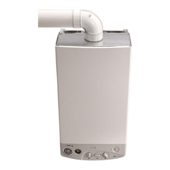
- Page 16 5.5 AIR/FLUE SYSTEM The FEB20E boiler comes supplied with a Ø 60 - 100mm coaxial air/flue kit. The maximum length of the combustion and intake pipes which may be used with the FEB20E boiler is three meters, measured from the 90° bend. Each extra 90° bend or two 45° bends, reduces the available length by 0.8m.
-
Page 17: Commissioning Instructions
6.- COMMISSIONING INSTRUCTIONS Before commissioning the appliance, the whole gas installation including the meter MUST be purged and test- ed for gas soundness. IMPORTANT: open all doors and windows, extinguish naked lights, and DO NOT SMOKE whilst purg- ing the gas line. Before commencing the commissioning procedure, ensure that the central heating system and the domestic hot and cold water system have been flushed. -
Page 18: Initial Operation
6.5 INITIAL OPERATION CONTROL PANEL. 1.- Programmable timer 2.- Heating temperature and pressure gauge 3.- Central heating temperature selector 4.- Main control switch 5.- D.H.W. temperature selector FEB -20E 6.- Green neon light (boiler ready) 7.- Orange neon light (burner functioning) 8.- Red neon light (boiler locked out) 6.5.1 Preliminary warnings - Checking all of the gas pipe joints and make sure that gas reaches the boiler (with the gas cock turned on) -
Page 19: Routine Servicing Instructions
6.6 FINAL CHECKS - Re-light and test for gas soundness - Set the C.H. and D.H.W. temperature selectors to the required settings. - Ensure that the time clock and/or room stat (if fitted) are set to the required setting (s). 6.7 USER’S INSTRUCTIONS Upon completion of testing the system, the installer should: - Give the ‘users Instructions’... - Page 20 7.2 BURNER AND HEAT EXCHANGER INSPECTION AND CLEANING The front of the sealed air box must first be removed (6 screws) and care should be taken to avoid damag- ing the seal. The combustion chamber cover can then be removed (4 screws) taking care not to damage the delicate insulation material inside.
-
Page 21: Wiring Diagrams
8.- WIRING DIAGRAMS 25 26 27 1. Filter 16. Ionisation electrode 2. Supply 17. High limit stat 3. Earth 19. D.H.W variable resistance 4. Fan 20. Heating variable resistance 5. Pump 21. D.H.W Thermistor 6. Ignition 22. Heating Thermistor 7. Burner solenoid valve 1 24. -
Page 22: Fault Finding
SELF DIAGNOSTIC FAULT CODES The FEB-20E has a built in self diagnostic fault finding system incorporated into the P.C.B. Should a fault develop on the boiler which could cause a situation liable for the operation of the boiler to become unsafe, then the boiler will fail safe by locking-out which is displayed via the 'red neon' on the control panel.
Need help?
Do you have a question about the FEB-20E UK ECOPLUS and is the answer not in the manual?
Questions and answers