Table of Contents
Advertisement
Quick Links
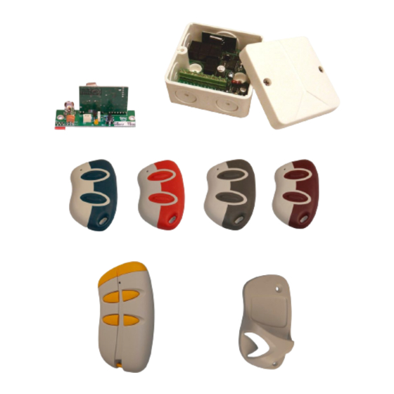
Radio receivers
type DB317 and DBR1-M4
User manual
Edition 5
Technical data
Dimensions (WxHxD)
Supply Voltage
Current Consumption
Temperature range
Status LED's
Outputs
Maximum No transmitters
Frequency
Weather protection
Compatibility
DAAB
BOX 125
S-284 22 PERSTORP
SWEDEN
Phone: +46 435 77 95 00
Fax: +46 435 77 95 29
E-mail: info@daab.nu
www.daab.nu
DB317
45x75x21 mm
via control panel
max 11mA
0 to 50°C
1 No LED
1 (internal signal)
85
433,92 MHz
Intended for mounting
Inside a cabinet
The receivers are compatible with DBR1 transmitters only.
Unit D5, Chaucer Business Park,
Kemsing, Kent, TN15 6YU
Phone: +44 (0)1732 765476
Fax: +44 (0)1732 765478
E-mail: sales@daab.co.uk
DBR1-M4
80x80x50 mm
12/24 VAC/VDC
max 41 mA
-20 to +70°C
4 No LED's
2 N/O, 2 N/O or
N/C contacts
85
433,92 MHz
IP65
DAAB
England
Advertisement
Table of Contents

Summary of Contents for DAAB DB317
-
Page 1: User Manual
Radio receivers type DB317 and DBR1-M4 User manual Edition 5 Technical data DB317 DBR1-M4 Dimensions (WxHxD) 45x75x21 mm 80x80x50 mm Supply Voltage via control panel 12/24 VAC/VDC Current Consumption max 11mA max 41 mA Temperature range 0 to 50°C -20 to +70°C Status LED’s... -
Page 2: Table Of Contents
There should be no other aerials or steel-work within the vicinity. WARNING! Only use the transmitter if you have full control over the door which will be used. The transmitters range can result in an involuntary operation. User manual DB317 and DBR1-M4 edition 5... -
Page 3: Description Of The Transmitters
• 2 button transmitter Red LED - Indicates a Function buttons transmission Battery tray Key-ring holder 2No CR2016 3v batteries • 4 button transmitter Red LED - Indicates a transmission Battery tray Function buttons Key-ring holder User manual DB317 and DBR1-M4 edition 5... -
Page 4: Description Of The Receivers
Output 2 Relay 2 Common Function: N/O or N/C Voltage supply Relay 2 N/C 12 VDC/VAC Relay 3 N/O Output 2 24 VDC/VAC Function: N/O Relay 3 Common Antenna Antenna connection Antenna, earth User manual DB317 and DBR1-M4 edition 5... -
Page 5: Mounting Receiver And Antenna
Mounting the receiver and antenna 1 channel receiver (DB317) 1. Switch off the electrical supply to the control panel EP103. 2. Gently press the connector on the card to the connector on EP103 panel marked X59. 3. Secure the card with two M3x4screws to the distance pieces on EP103 panel. -
Page 6: Commissioning/Coding
2. Press the button again to select which channel is to disabled (LED is lit above the chosen output). 3. Transmit a signal with the channel to be disabled. Repeat for any other channel to be disabled. The receiver confirms reception by the two LED’s D3 and D4 flashing twice. User manual DB317 and DBR1-M4 edition 5... -
Page 7: Service Fault Finding
Press the self-teach button until the LED is lit. 2 a. (DB317) Release the button and press again; the LED D1 flashes 3 times. 2 b. (DBR1-M4-1) Release the button and press again; LED’s D3 and D4 flash 3 times. -
Page 8: Accessories
002611 art no. 002663 art no. 002666 Dipole antenna for receiver, Radio control receiver Radio control receiver including mounting bracket and DBR1 type DB317. DBR1-M4. 3 meters of coaxial cable 1 channel 4 channels art no. 001572 art no. 002606 art no.
Need help?
Do you have a question about the DB317 and is the answer not in the manual?
Questions and answers