Advertisement
Table of Contents
- 1 Table of Contents
- 2 Important Safety Information
- 3 Amplifier Overview
- 4 Mechanical Installation
- 5 Mains Power Connection
- 6 Audio Signal Input Connection
- 7 Audio Power Output & Load Connection
- 8 Amplifier Load Protection
- 9 Amplifier Range Technical Specifications
- 10 Amplifier Application
- 11 Warranty Information
- 12 Amplifier Servicing & Warranty
- Download this manual
Advertisement
Table of Contents

Summary of Contents for FFA FFA-4004
- Page 1 FFA Series Amplifiers OEM variants Operation Manual Issue 1.1 Sept 2012...
-
Page 3: Table Of Contents
Contents Important safety information pg 4 Amplifier overview pg 5 Mechanical installation pg 6 Mains power connection pg 7-8 Audio signal input connection pg 9 Audio power output & load connection pg 10-11 Amplifier load protection pg 12 Amplifier range technical specifications pg 13 Amplifier application pg 14... -
Page 4: Important Safety Information
Important safety information DO NOT REMOVE THE FFA-4004, FFA-6004, FFA-6000, FFA8000, FFA-10000 CHASSIS COVERS. THERE ARE NO USER SERVICEABLE PARTS INSIDE THE UNIT. REFER SERVICING TO QUALIFIED PERSON ONLY. THE FFA-4004, FFA-6004, FFA-6000, FFA-8000, FFA-10000 MUST BE EARTHED. IT SHOULD NOT BE NECESSARY TO REMOVE ANY PROTECTIVE EARTH OR SIGNAL CABLE SHEILD CONNECTIONS TO PREVENT GROUND LOOPS. -
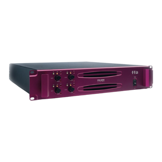
Page 5: Amplifier Overview
Amplifier overview The FFA series of audio power amplifiers are high fidelity, high power output professional power amplifiers. FFA amplifiers are ideally suited for a variety of professional audio applications. We have thoroughly tested our products during the design phase and once we are satisfied that the design criteria has achieved we undertake extensive real world field trials to further prove the design. -
Page 6: Mechanical Installation
Mechanical installation The amplifier is built around the industry standard 2 RU (88mm) high and 19” wide rack space. The amplifier requires a depth of 500mm from rack ear fixing points to rear of unit. Rear rack ear brackets are built in as standard, please use these to provide maximum protection for your investment. -
Page 7: Mains Power Connection
Warning! This appliance must be earthed at all times. The FFA-4004 and FFA-6004 have a single Neutrik powercon power inlet which requires a maximum of 16A, 230V ac 50/60 Hz. The FFA-6000, FFA-8000 and FFA-10000 amplifiers have two individual power supplies fitted with a Neutrik powercon mains inlet for each amplifier channel. - Page 8 POWERING UP The FFA-4004 and FFA-6004 have a single power on switch located on the right side of the front panel with green LED indicator for ‘power on’ . The FFA-6000, FFA-8000 and FFA-10000 have 2 power on switches one for each channel and green LED power on indicators.
-
Page 9: Audio Signal Input Connection
Audio signal input connections Each amplifier channel has an input (female XLR) and parallel link (male XLR). The inputs are 20k Ohm electronically balanced. The ‘link’ XLR can be used either to link channel A and B together to provide a ‘mono’ signal (for example mono bass signals) or to carry a signal to a further adjacent amplifier. -
Page 10: Audio Power Output & Load Connection
NEUTRIK NL4 OR NL2 TYPE CABLE CONNECTORS ARE TO BE USED FOR CONNECTING THE AMPLIFIER TO LOUDSPEAKERS. FFA-4004, FFA-6004. FFA-4004 and FFA-6004 amplifiers are designed to drive a minimum of 4 Ohms load per channel. A typical load for each amplifier channel would be 2 x 8 Ohm loudspeakers connected in parallel. - Page 11 Audio output and load connection FFA-6000, FFA-8000, FFA-10000. FFA-6000, FFA-8000 and FFA-10000 amplifiers are specifically designed to drive down to a minimum of 2 Ohms. A load example for each channel could be 4 x 8 Ohm bass drivers connected in parallel.
-
Page 12: Amplifier Load Protection
FFA air flow convention is used as we believe this is the best way to remove hot air away from the amplifier and the rack it is installed within. The rear of the amplifier rack can be crowded with cables and possibly patch panels which can impede the hot air as it is expelled from the amplifier. -
Page 13: Amplifier Range Technical Specifications
Ampilifier Specifications -3dB Clip -3dB Clip -3dB Clip -3dB Clip Protect Protect FFA - 6004 Protect Protect FFA - 4004 FFA - 6000 FFA - 8000 FFA -10000 -3dB Clip -3dB Clip 4 x 1 5 0 0 W A T T... -
Page 14: Amplifier Application
HF, 4 ohm drive. Suitable Applications: FFA-6000 Small low mid or smaller bass 2x12”, 2x 15”, 2x18” – 2 Ohm drive Medium to large full range loudspeakers 10”-15” drivers + 1” 1.5” HF FFA-8000 Medium low mid 2x12”, 2x 15”, 2x18” – 2 Ohm drive Low mid, high and HF in larger multi way systems installed or touring. -
Page 15: Amplifier Servicing & Warranty
fluid or related substances that may contaminate the unit are not covered by this warranty. No other warranty is expressed or implied. If a fault is found on your FFA amplifier. It should returned to the dealer where bought in its original shipping carton pre-paid. The unit will be returned when repaired. - Page 16 Dealer address: Dealer tel no: Dealer contact name: Invoice/receipt no: Postcode: Date of purchase: FFA serial numbers: rades Description Act: FFA have a policy of continued product development and accordingly reserve the right to change features and specifications without prior notice.
- Page 18 www.fullfataudio.com Full Fat Audio Ltd Unit 4, The Granary, Fairclough Hall Farm, Weston, Hitchin, Hertfordshire, SG4 7DP UK Tel: +44 (0)1462 790700 email: info@fullfataudio.com...
Need help?
Do you have a question about the FFA-4004 and is the answer not in the manual?
Questions and answers