
Related Manuals for Homony HBA-5120A

Summary of Contents for Homony HBA-5120A
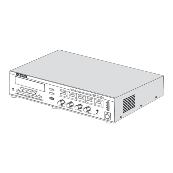
- Page 1 Five Zone Management Amplifier Installation and Operating Manual HBA-5120A HBA-5240A...
-
Page 2: Table Of Contents
Table of Contents 1. IMPORTANT SAFEGUARDS ………………………………………………… ………………………………………………… 2. HANDLING PRECAUTIONS 3. INSTALLATION PRECAUTIONS …………………………………………… 4. GENERAL DESCRIPTION … …………………………… …… ………………… ……………………………………………………………………… 5. FEATURES ……………………………………… 6.NOMENCLATURE AND FUNCTIONS FRONT …………………………………………………………………………… ……… …… ……… ………… … …………………………… ……………… REAR ……………………………… 7. -
Page 3: Important Safeguards
1. Important Safeguards Read instructions—Before the system is installed and operated all the safety instructions shouldbe read Retain instructions—For future reference the safety instructions and instructions for use should beretained. Heed warnings—User should adhere all warnings on the unit and in the installation and operationinstructions. -
Page 4: About This Manual
If the unit does not run normally by following the instruction for use. Only adjust those controls that arecovered by the instructions for use, because an improper adjustment of other controls may cause damageand will often require extensive work by a qualified technician to restore the units to their normal operation.... -
Page 5: Installation Precautions
HBA-5120A/HBA-5240A To clean, be sure to switch off the power supply to the unit first, then wipe with a dr y cloth. When the unit gets ver y dirty, use a cloth damped in a neutral cleanser. Never use benzene, thinner or chemically-treated cleaning cloth because such volatile liquids could deform or discolor the unit. -
Page 6: General Description
Caution ■ If there is a need to open the amplifier's top cover when performing work such as mounting optional boards or setting switches, ensure it is done by a qualified ser vice technician. ■ Make sure to switch the power off before performing any work on the amplifier such as the caseabove. -
Page 7: Nomenclature And Functions
6.NOMENCLATURE AND FUNCTIONS [Front] The HBA-5120 is shown in the figure. The features and functions of HBA-5240A are the same as the above figure. 1.LCD Display 8.Zone Selector [ZONE] Displays the current status and operating Individual zones may be switched on or off instructions of the system out of five zones 2.IR Signal indicator... -
Page 8: Rear
[Rear] The HBA-5120 is shown in the figure. The features and functions of HBA-5240A are the same as the above figure. 1.Loudspeaker Terminal 7.AUX Input A RCA pin jack . Connect other music sources [4~16 Ω, 70/100V,Z1~Z5] Screw terminal, connect 4~16 Ω f or to this jack . -
Page 9: Syestem Configuration
7. SYESTEM CONFIGURATION The system is easy to operate. Users can get a further understanding of the setup of HBA-5120A/ HBA-5240A by reading the following figure and descriptions. Amplifier Sound Source Equipment Am Ant Fm Ant System Configuration Steps: Step 1: Connect with sound source equipment, for example, connect source equipment to AUX Input;... -
Page 10: Appendix
8. APPENDIX 8.1 Power Cable 8.2 Loudspeaker Connection 8.2.1 Please use screwdriver to fix the speaker line with the loudspeaker connectors tightly. Other wise, the imperfect connection may result in loudspeaker noise. 8.2.2 After the speaker line is connected with the loudspeaker connectors, check carefully whether metal part is excessively exposed. - Page 11 8.2.4 When connecting the speaker line to the output terminals, please be aware of corresponding broadcasting area of each output terminal. Four Terminal Connector : COM, 4-16 Ohm, 70V, and 100V 8 Ohm 4 Ohm 4O h m 8O h m 8O h m 8O h m 8O h m...
-
Page 12: Microphone
8.3 Microphone 8.3.1 Connect standard RCA 6.35 Plug Microphone to the MIC input, then the microphone can work . 8.3.2 Connect standard XLR Plug Microphone to the MIC input, then the microphone can work . - Page 13 8.4. Sound Source Input and Output AMPLIFIER 8.4.1. Connect the sound source equipment with AUX input 8.5 Rack Mounting 8.51 The amplifier is delivered for table top use, but you can mount it in a 19" rack . 8.52 If you mount the amplifier in a rack , you must: ★...
- Page 14 8.6 CD/DVD Drive Input 8.6 1. This player can play DVD/CD/Mp3 disc...
- Page 15 这 页 起 和 后 面 的 所 有 页 请 翻 译 , 谢 谢 ! ! ! 9 Microphone 9.1 Adaptive Microphone HCM-001MH [Front] The exterior and function of HCM-001MH is the same as above figure 1.Microphone Please put sound source close to the zone to ensure a clear input 2.Switch Press the button to turn on the microphone for paging 3.Status Indicator Light...
- Page 16 9.2 Microphone 9.21 Plug standard XLR connector into the MIC input. 9.22 Plug standard XLR connector into the Microphone output. 9.23 A 3 meter cable with standard XLR connector is provided with Microphone. 9.24 DIY XLR connector If customers make XLR connectors themselves, please refer to the following cabling definitions: Line 2 is +, Line 3 is -,Line 1 is ground.
- Page 17 9.25 When connect microphone with standard XLR connector, please make sure the phantom power is turned on, otherwise the microphone will not work. If phantom power is not available, please plug in 9v~12v 100mA~1A power. 9.3 Microphone power supply Power Supply DV 9V~12V DC 9v~12v power is suitable for Microphones Phantom power can be switched on when there is no external power supply available surrounded...
-
Page 18: Remote Control
10.Remote Control MUTE SELECT MODE AUTO AUTO/NORMAL MEMORY AEARCH 1. Mute 2. CD/DVD In / Out 3. Number Keys to select the program when playing Mp3, CD/DVD, or AM/FM. 4. Audio Source Selector 5. Search forward when playing AM/FM. 6. Search back when playing AM/FM. 7. -
Page 19: System Diagram
11. System Diagram... -
Page 20: Specification
12. Specification Mode HBA-5120A HBA-5240A Rated Power 120 W 240 W Weight 11.2KG 15.4KG Dimensions 405mm*430mm*100mm 405mm*430mm*100mm Power Supply 230Vac ± 10%, 50/60 Hz Protection 5A ac fuse Distortion < 1% @ rated Outputs, 1kHz Bass Control -14/+10 dB @ 100 Hz... - Page 21 13. Replace Fan Diagram 1.Take out fan 2.Replace with a new fan 1 . P W M c o o l i n g , i n t e l l i g e n t c o n t r o l , f a n s i z e : 8 0 x 8 0 , 1 2 V , D C P o w e r S u p p l y . 2 .
- Page 22 Warning 1. Do not block the ventilation slots. 2. Do not install in locations exposed to rain, heavy dust, heavy moisture, heat radiation and strong vibration. 3. Ensure well earth connection. 4. Use AC outlet compatible to the powerplug of this equipment only.
Need help?
Do you have a question about the HBA-5120A and is the answer not in the manual?
Questions and answers