
Related Manuals for Sailor HC4500

Summary of Contents for Sailor HC4500
-
Page 1: Operating Instructions
SAILOR HC4500 MF/HF CONTROL UNIT Operating Instructions Distress Calls, see page ii. List of contents, see page 1. -
Page 2: Distress Acknowledgement
Quick DISTRESS Call 1. If off or STANDBY: press ON/OFF. 2. Open DISTRESS lid. Press the DISTRESS button seconds to transmit 3 - 2 - 1 - 3. Press DISTRESS TYPE : Distress RELEASE until RELEASE is displayed MSG. : Undesignated : N57°01 W009°53 Time : 13:01 UTC... -
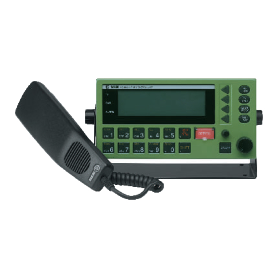
Page 3: What Is What
What is What? 1. Display. 9. TEL/DSC function switch. 2. Indicator lamps. Condition when lit: In TEL mode radiotelephone parameters are shown and Transmitting. selected. CALL: DSC (see button 9) call for you received. In DSC mode DSC parameters are shown and selected. ALARM: Alarm call received. -
Page 4: Introduction
MF/HF communication and safety procedures. For an explanation of Automatic Gain Control DSC, see page 2. Amplitude Modulation Automatic Repetition reQuest Your SAILOR HC4500 MF/HF is a part of the modular system 4000 CLRF Clarify which also includes a HF single sideband radiotelephone. It has Control Unit built-in MF/HF telex if connected to a PC and/or a printer. -
Page 5: Table Of Contents
Advanced DSC Calls ............15 Contents Changing a Function ............17 Quick DISTRESS Call ............ii The Function Tree ............ 18 DISTRESS Acknowledgement ..........ii GMDSS Radiotelex Terminal ..........19 What Is What? ..............iii Introduction ..............19 Introduction ................. iv Keyboard Indicator Lamps .......... -
Page 6: Mf/Hf Fundamental Info
MF/HF Fundamental Info Propagation of MF and HF Radio Waves. DSC (Digital Selective Calling) is an automatic calling system which allows a specific station to be contacted and made aware that a MF/HF radiocommunications provide a medium and long range station wishes to communicate with it. -
Page 7: Basic Functions
Setting Transmitter Power Level Basic Functions 1. Press the Shift key followed by the Power Key. Switching ON/OFF 1. Press the ON/OFF button. The output power is set to HIGH, MED or LOW. Repeat until the desired setting is reached. Setting Backlight Level 1. -
Page 8: Manual Call Functions
Manual Call Functions Telephony Channel Display Functions: Name of station if selected. Channel number. Soft keys LYNGBY FREQ Switches to Frequency display for viewing or altering frequencies. 4 1 8 STATION Switches to Station display for selection of another station. Steps to the next lower channel number of the station. -
Page 9: Station Display Functions
Station Display Functions: Name of station MMSI number of station Soft keys SELECT Selects the station and switches to Channel display for choice of channel number. STATION TABLE CANCEL Returns to Channel display without selecting the station. NAME LYNGBY CALL SIGN Selects previous station. -
Page 10: Two-Tone Alarm Signal
Two-tone Alarm Signal To switch to the Two Tone Alarm Signal display: Press the Shift key followed by the Alarm key. Two-tone Alarm Display Functions: Soft keys Press the START button FREQ Returns to frequency display. Starts test of the alarm signal generator. TEST seconds to send alarm Starts transmission of the two tone alarm signal. -
Page 11: Dsc Main Buttons
DSC Main Buttons To switch between the DSC STATUS and telephony displays: press TEL/DSC. Soft keys CHANGE DSC STATUS Changes calling watch frequencies. WATCH Switches between calling watch On/Off Distress Watch: 2 12 16 MHz Views watch frequencies. Calling Watch: 2 -- MHz VIEW FREQ Changes distress frequency used default for quick distress calls. -
Page 12: Calling Watch
Calling Watch To switch to DSC screen: press TEL/DSC. Soft keys CHANGE DSC STATUS Changes calling watch frequencies. WATCH Switches between calling watch On/Off Distress Watch: 2 12 16 MHz Views watch frequencies. Calling Watch: 2 -- MHz VIEW FREQ Changes distress frequency used default for quick distress calls. -
Page 13: Dsc Display Operation
DSC Display Operation Receiving an Individual DSC Call When calling watch is on, your MF/HF set is constantly scanning the selected DSC channels for incoming DSC calls. Lift the handset and press PTT to connect to the caller. Lift HANDSET to connect Individual call received Press VIEW to read out the call. -
Page 14: Receiving Distress Call
Receiving DISTRESS Call When switches on your MF/HF set is constantly scanning all DSC distress channels for incoming DSC distress calls. Distress call received Press VIEW to read out the call. VIEW ABORT Press ABORT to return to TEL screen FROM: 21900100 CALL CONTENT Time:... -
Page 15: Calling A Ship
Calling a SHIP Press Tx CALL SHORE Select type of call: Select a SHIP call. SHIP DISTRESS MORE Key in the nine digit MMSI number of the wanted ship. Key in the ship ACCEPT Accept the number. MMSI number < MEMORY A sub menu where a pre-programmed ship can be selected. -
Page 16: Calling A Shore Station
Calling a SHORE Station Press Tx CALL SHORE Select type Select a SHORE call. of call: SHIP DISTRESS MORE Key in the nine digit MMSI number of the wanted coast station. Key in the coast ACCEPT Accept the number. station MMSI number <... -
Page 17: Address Book
Address Book This MF/HF set is designed with self explaining menues. The four soft keys on the right side of the display refer to the display text. Open the addr book menu. Lower left side of the display is the data area. Right side shows the Upper left side of the function of the soft keys. -
Page 18: Using Two Control Units
If for instance control unit #2 has sent an individual DSC call, control Using Two Control Units unit #2 is to receive and respond to the acknowledgement call that may follow. You can connect two control units to the system. However, it can If a call comes in when both control units are in the DSC Status only be controlled by one control unit at a time. -
Page 19: Advanced Dsc Calls
Advanced DSC Calls Extended DSC calls make it possible for you to control the call completely within the international rules, including the possibility of sending data or fax from optional equipment connected to your MF/ HF set. To start an extended call, select EXTENDED as the ‘Type of call’ in the Tx menu below, and then continue in the Extended calls menu on next page. - Page 20 EXTENDED Tx call started from “EXTENDED” in the table on the previous page. Enter correct data instead of examples shown in italics : Type of call Address Options Category Telecom 1 Telecom 2 Add. msg. Ackn. INDIVIDUAL Shore: 001234567 No info: Call shore station Routine SSB telephony No info Shore phone: 98765432: Call Phone No.
-
Page 21: Changing A Function
Changing a Function There are a large number of function settings available, selectable from a function tree, see the next page. This chapter only deals with the principles of how to use the function tree. An example: Changing the Display Contrast Press SHIFT and FUNC to enter function menu. -
Page 22: The Function Tree
The Function Tree Menu Submenu Level 1 Submenu Level 2 Parameters User Display Contrast 0 to 7. High Contrast = 7 Sound Earpiece level Attenuation Level 0 - 15 Alarm level Attenuation Level 0 - 15. Version SW versions for all modules Print DSC Printer On/Off Config... -
Page 23: Gmdss Radiotelex Terminal
GMDSS Radiotelex Terminal Introduction The GMDSS Radiotelex Terminal is an option used for handling also leave ‘standby’ and enter ‘phasing’ state by transmitting an transmission/reception of telex messages over radio. The terminal appropriate control character. After having verified the other station’s consists of a printer and a keyboard, connected to the transceiver identity both stations will proceed to ‘traffic’... -
Page 24: Keyboard Indicator Lamps
Break (F9): Terminates a connection. Keyboard Indicator Lamps Responds by printing ‘Breaking connection’. ‘Standby’ Steady light indicates that the terminal is If pressed during transmission of an edited ready. message this is terminated. Press once more Flashing light indicates that the printer is off to terminate the connection. -
Page 25: Switching On
message may now be transmitted by pressing carriage return (¬ Switching On Enter) followed by the message to be transmitted, either typed in Press F10 and switch on the printer (The ‘Select’ printer indicator directly from the keyboard, or recalled from the text memory by must be on). -
Page 26: Receiving A Message
The process may be repeated if ‘N’ is pressed; the modem set-up Receiving a Message mode is left if ‘Y’ is pressed. Reception is possible whenever the terminal is on, indicated by steady light in the ‘Standby’ keyboard indicator. The radio must be The answer back of the modem is generated by combining the 5-digit set to telex mode and to the desired working channel. -
Page 27: Example Of Fec Transmission
Example of FEC Transmission Example of ARQ Transmission to a Assuming the GMDSS telex terminal is in Standby and the radio is Coast Station set up to telex mode and to the desired frequencies following a DSC When the GMDSS telex terminal is on, indicated by the ‘Standby’ Distress alert call, proceed as follows: keyboard indicator lamp, and the radio is set up to the desired working channel (and, if requested by the coast station, free signal... - Page 28 Send own answer-back by pressing the DE key: 123456789 abcd x The message is now transmitted by pressing carriage return (¬ Enter) followed by the message to be transmitted, either typed in directly from the keyboard, or recalled from the text memory by pressing the MESSAGE key: this message is typed in directly from the keyboard or recalled from the text memory.
Need help?
Do you have a question about the HC4500 and is the answer not in the manual?
Questions and answers