Table of Contents
Advertisement
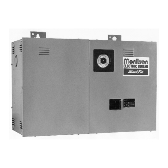
MODEL EH ELECTRIC BOILER
EH8-135S through EH-40-135S 3 wire 120/208V, 120/240V single phase
EH-12-345S through EH-40-345S 4 wire 120/208V three phase WYE
OPERATION AND INSTALLATION INSTRUCTIONS
CONTENTS . . . . . . . . . . . . . . . . . . . . . . . . . . . . . . . . . . .PAGE
Description . . . . . . . . . . . . . . . . . . . . . . . . . . . . . . . . . . . . . . . . . 2
Mounting . . . . . . . . . . . . . . . . . . . . . . . . . . . . . . . . . . . . . . . . . . . 2
Piping . . . . . . . . . . . . . . . . . . . . . . . . . . . . . . . . . . . . . . . . . . . . . 2
Air Eliminator and Expansion Tanks . . . . . . . . . . . . . . . . . . 2
Flow Switch . . . . . . . . . . . . . . . . . . . . . . . . . . . . . . . . . . . . . 2
Bypass . . . . . . . . . . . . . . . . . . . . . . . . . . . . . . . . . . . . . . . . . 2
Wiring . . . . . . . . . . . . . . . . . . . . . . . . . . . . . . . . . . . . . . . . . . . . . 2
Wall Thermostat Flow Switch and Circulator . . . . . . . . . . . 2
Service Connections and Electrical Ratings . . . . . . . . . 3-4
Typical Piping . . . . . . . . . . . . . . . . . . . . . . . . . . . . . . . . . . . . . . 5
Typical Zone Valve Wiring . . . . . . . . . . . . . . . . . . . . . . . . . . . . . 6
Start-up . . . . . . . . . . . . . . . . . . . . . . . . . . . . . . . . . . . . . . . . . . . . 7
Fill System . . . . . . . . . . . . . . . . . . . . . . . . . . . . . . . . . . . . . . 7
Air Elimination . . . . . . . . . . . . . . . . . . . . . . . . . . . . . . . . . . . 7
Bypass Flow Adjustment . . . . . . . . . . . . . . . . . . . . . . . . . . 7
Check for Proper Boiler and System Operation . . . . . . . . 7
Operation (models equipped with seq. control system) . . . . . . 7
Periodic Inspection . . . . . . . . . . . . . . . . . . . . . . . . . . . . . . . . . . . 7
Appendix A & B . . . . . . . . . . . . . . . . . . . . . . . . . . . . . . . . . . . . . 8
Heating Contractor
Address
Phone Number
IMPORTANT:
This manual must be left with owner and should be hung
on or adjacent to the boiler for reference.
Boiler Model Number
Boiler Serial Number
Installation Date
HG 10/08-10/08-2m Printed in Canada
Publication No. EH-40
Part No. 79-0820
Rev.B
Advertisement
Table of Contents

Summary of Contents for StantFin Monitron EH
-
Page 1: Table Of Contents
MODEL EH ELECTRIC BOILER EH8-135S through EH-40-135S 3 wire 120/208V, 120/240V single phase EH-12-345S through EH-40-345S 4 wire 120/208V three phase WYE OPERATION AND INSTALLATION INSTRUCTIONS CONTENTS ........PAGE Description . -
Page 2: Description
DESCRIPTION Bypass The Monitron boiler is a low pressure hot water heating electric The bypass shown must be set so that a sufficient amount of boiler. The heating elements are sheathed resistance type. The water can circulate through the boiler when all zone valves are heat exchanger is cast-iron. -
Page 3: Service Connections And Electrical Ratings
Wire an external zone valve transformer to the "A-B" termi- B. Draw power feeder cable (90°C [75°F]minimum) and nals if zone valves are used. These terminals provide a conduit through service K.O. provided on side, top constant 120 volts and can alternately be used to power the or bottom. - Page 4 TYPICAL WIRING DIAGRAM For three phase, third power leader lug is added. FOR OUTDOOR THERMOSTAT OR TO ZONE VALVE TRANSFORMER OTHER CONTROL TO MODULATE OR FOR CONSTANT CIRCULATOR BOILER IN MILDER WEATHER OPERATION WHEN DESIRED Figure 2: Typical Wiring Diagram for Models equipped with Circuit Breakers TYPICAL WIRING DIAGRAM For three phase, neutral lug is used for third power feeder lug...
-
Page 5: Typical Piping
32mm (1-1/4") SUPPLY TAPPING PRESSURE, 32mm (1-1/4") RETURN TAPPING Figure 4. Typical Single Zone Piping 32mm (1-1/4") SUPPLY TAPPING ALTITUDE, PRESSURE, THROTTLING TEMPERATURE VALVE GAUGE 32mm (1-1/4") RETURN TAPPING Figure 5. Typical Multi-Zone Using 2-Way Valves 32mm (1-1/4") SUPPLY TAPPING PRESSURE, 32mm (1-1/4") RETURN... -
Page 6: Typical Zone Valve Wiring
LINE VOLTAGE (120V) TERMINAL BLOCK FOR OUTDOOR THERMOSTAT IF USED OR JUMPERED IF NOT. VOLTAGE (24V) TERMINAL BLOCK Figure 7. Typical Zone Valve Wiring MULTIZONING OF BOILER; PUMP ZONING SYSTEM USING R845A RELAY BOILER Figure 7a. Multizoning of boiler; pump zoning system using R845A relay. -
Page 7: Start-Up
START-UP OPERATION NOTE: Make sure that all circuit breakers ahead of and at the (Models equipped with Sequential Control System) boiler are OFF. These models contain a "S" in the model number which is located on the rating plate on the top surface of the boiler. Fill System See Figures 4 through 6 for suggested purge valve and block- IMPORTANT:... - Page 8 Appendix A Thermostat Heat Anticipator Settings Fixed anticipator thermostats are not adjustable. Adjustable anticipator thermostats, depending on thermostat model, may be adjustable from a . 18 to a .9 setting by moving a pointer on the anticipator. The higher the anticipator setting (towards .9) the longer it will take for the thermostat to respond to a change in room temperature.
Need help?
Do you have a question about the Monitron EH and is the answer not in the manual?
Questions and answers