
Related Manuals for Days Strider MD 3


Summary of Contents for Days Strider MD 3
- Page 1 S T R I D E R NURSING BEDS PFLEGEBETTEN OPERATING MANUAL MD 3 and MD 4 3-wheel and 4-wheel version Order number: E1-04-049-001...
- Page 3 S T R I D E R M D Introduction With the Strider MD, you have now purchased a product which has been manufactured in accordance with the newest technical capabilities and based on the highest operating comfort. We have placed great value on the simplest possible operation and long service life in both construction and material selection.
-
Page 4: Table Of Contents
S T R I D E R M D Contents 1.0 Safety instructions ................. 8 1.1 Symbols used ................8 1.2 Intended use ................8 1.3 General Information ..............9 1.4 Safety when driving ..............10 1.5 Safety during transport, assembly and maintenance ....11 1.6 Safety when handling batteries .......... - Page 5 S T R I D E R M D Contents 8.2 Seat belt - adjusting for length and putting on ......37 8.3 Turning the seat ................. 38 8.4 Switching the strider on ............. 38 8.4.1 Operation indicator and fault display ....... 38 8.5 Adjusting the speed ..............
- Page 6 S T R I D E R M D Contents 13.12 Insurance ................. 50 13.13 Approval for road traffic use ............. 50 14.0 Transporting the strider ..............51 14.1 Transport information ..............51 14.2 Transporting the complete scooter ..........51 14.3 Preparation for transport - separating components .....
- Page 7 S T R I D E R M D Contents 18.4.3 Replacing bulbs in rear lights and rear indicators .... 78 18.5 Lighting - 4 wheel version ............79 18.5.1 Replacing bulbs in headlights and rear light ....79 18.5.2 Replacing bulbs in front/rear indicators ......80 18.6 Fuses ..................
-
Page 8: Safety Instructions
You will also find information about dealing with the product under this symbol. Intended use The Days Healthcare scooter is constructed for use both indoors and outdoors (Class B, European standard EN 12 184). It is intended to increase the mobility of persons who are both physically and mentally capable of assessing any driving situations correctly and reacting correspondingly to them at any time. -
Page 9: General Information
• Observe maximum loading = see Specifications • Only use accessories and spare parts authorized by Days Healthcare. • The scooter is only authorized for transport of one person. • Do not carry out any seat adjustments while driving. -
Page 10: Safety When Driving
S T R I D E R M D Safety information Safety when driving Risk of accidents! • Check correct functioning of the brakes and lighting unit (indicators, headlights) before every journey. • Always use lights when visibility is restricted, either by day or by night. -
Page 11: Safety During Transport, Assembly And Maintenance
S T R I D E R M D Safety information Danger due to unintentional movement! • Always turn the scooter off using the keyswitch if you: - want to get on or off - intend to stop for long periods - are putting the scooter away. -
Page 12: Safety When Handling Batteries
S T R I D E R M D Safety information Safety when handling batteries Fire hazard! • Do not cover the battery charger and ventilation slot while charging batteries. • Only use the battery charger in well-ventilated areas. Risk of accidents! •... -
Page 13: Versions
S T R I D E R M D Versions 2.0 Versions 3-wheel version with standard 3-wheel version with captain’s seat seat 4-wheel version with 4-wheel version with captain’s standard seat seat 3.0 Extent of delivery The following items are included in delivery in addition to the Strider: 1. -
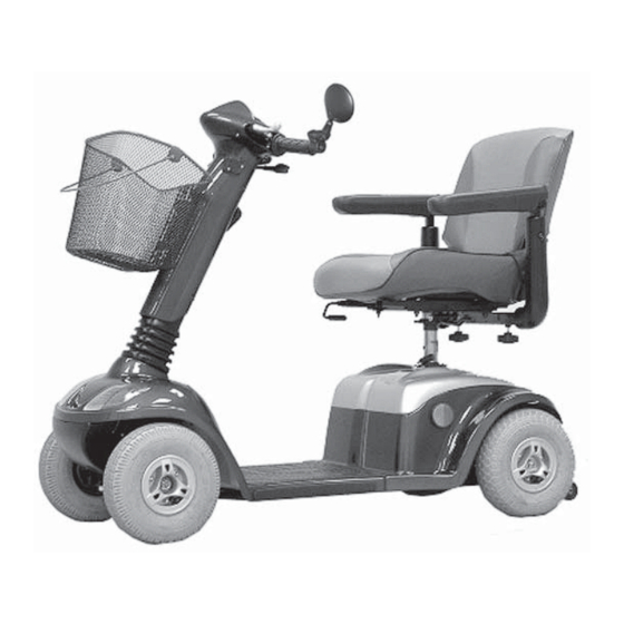
Page 14: Components
S T R I D E R M D Components 4.0 Components Dashboard The Strider with controls Rear view Seat unit with mirror armrests Shopping basket Drive unit Tiller covers Indicators and Indicators headlight and rear light Steering Anti wheel tipper The dashboard - displays and controls Operation indicator... -
Page 15: Brief Instructions
S T R I D E R M D Brief instructions 5.0 Brief instructions The following brief instructions should enable people to quickly get used to operating the scooter after a long period of non-use and to refresh existing knowledge of operation. It is imperative that you follow the instructions given in the main manual! Driving the Strider... - Page 16 S T R I D E R M D Brief instructions 5.) Check the battery 6.) Set the maximum speed charging state = lowest possible driving speed (approx. 1.5 mph) = highest possible driving speed (approx. 4 mph) 7.) Driving Operate the drive lever slowly until the required speed has been reached The drive lever position controls the speed variably right up to maximum...
-
Page 17: Transporting The Strider
S T R I D E R M D Brief instructions Transporting the Strider Dismantling the Strider (stages 1 to 10) 1.) Remove the seat 2.) Remove the rear panelling 3.) Remove the lighting cable 4.) Remove the battery plug 5.) Remove the battery belts and 6.) Fold the tiller down batteries... - Page 18 S T R I D E R M D Brief instructions 7.) Separate the front connector 8.) Unlock the drive unit 9.) Tilt the drive unit away 10.) Remove the chassis Reassembling the Strider (Stages 10 to 1) The Strider dismantled: 1.
-
Page 19: Setting Up The Strider
S T R I D E R M D Adjusting the seat height 6.0 Setting up the Strider The following passage describes how to set up your Strider in order to ensure that you have a comfortable and safe drive. Adjusting the seat height NOTE! The seat must be removed from the... - Page 20 Adjusting the seat height S T R I D E R M D Press the locking device (a) on the plug and disconnect the electric cable connecting plug (2) to the rear lights and rear indicators. Remove the rear panelling. Adjusting the seat height: Tools required: 2 x ring spanner, size 12 mm...
- Page 21 S T R I D E R M D Adjusting the seat height Adjusting the seat The seat height (h) is adjusted using the support four holes (B1 - B4) in the seat support. Pull the seat support (6) out as far as the required height until the correct hole (B1-B4) appears in the seat tube hole (7).
- Page 22 Adjusting the seat height S T R I D E R M D Connecting the light cable Fixing the rear panelling: Plug in the light and indicator cable connecting plug (2). Fixing the rear panelling Place the rear panelling onto the drive unit from above.
-
Page 23: Adjusting The Seat Position - Standard Seat
S T R I D E R M D Adjusting the seat position Adjusting the seat position - standard seat 6.2.1 Adjusting the distance between seat and Moving the tiller seat Pull the locking lever (1) upwards and move the seat forwards or backwards to the required distance. -
Page 24: Adjusting The Armrest Height
S T R I D E R M D Adjusting the seat position 6.2.3 Adjusting the armrest height Loosening the fixing Tools required: 1 x Allen key (size 5 mm) Loosen the Allen screw (4) and remove. The armrest height is adjusted using four holes in the armrest support (b). -
Page 25: Adjusting The Seat Position - Captain´s Seat
Adjusting the seat position S T R I D E R M D Adjusting the seat position - captain´s seat 6.3.1 Adjusting the distance between seat and Moving the tiller seat Pull the locking lever (1) upwards and move the seat forwards or backwards to the required distance. -
Page 26: Adjusting The Backrest Inclination
S T R I D E R M D Adjusting the seat position The armrest height is adjusted using four holes in the armrest support (b). The height can be adjusted in stages of 10 mm. Adjusting the Pull the armrests upwards to the required armrest height height until the hole in the armrest support appears through the hole in the... -
Page 27: Adjusting The Headrest Hight
S T R I D E R M D Adjusting the seat position 6.3.5 Adjusting the headrest hight Adjusting the Press the locking device (8) and push headrest the headrest upwards or downwards into the required position (9). Adjusting the tiller angle Always adjust the tiller so that you can reach all displays and controls easily at any time. -
Page 28: Information About Safe Strider Driving
S T R I D E R M D Driving information 7.0 Information about safe Strider driving Always carry out the safety information described in chapter 1.5 “Safety during driving“! Driving the Strider is very simple and after a few practice sessions you will find it very easy. -
Page 29: Overcoming Obstacles
S T R I D E R M D Driving information • Avoid driving across an incline (always try to drive in the direction of the incline / decline). Tipping There is an increased danger of tipping hazard! when climbing or descending gradients if: •... - Page 30 S T R I D E R M D Driving information Please observe the following points to make sure that your Strider doesn’t tip over while climbing obstacles: • don’t try to drive over obstacles which are too high example: kerbstones remedy: always climb up kerbstones at lowered entry areas such as driveways.
-
Page 31: Driving Information - Overcoming Kerbs
S T R I D E R M D Driving information 7.2.1 Driving Information – Overcoming kerbs Risk of accidents! Neogating kerbs needs some practice. • Please observe the maximum obstacle heights of 8 cm. • Please start practicing kerb climbing with small kerbs. Approach at a right angle Approach the kerb at a right angle. -
Page 32: Overload Protection - Motor Protection
S T R I D E R M D Driving information Overload protection - motor protection The overload protection switches the drive off if the motor becomes overloaded by trying to climb over too high an obstacle such as a kerbstone, or if you try to climb too steep of an incline. -
Page 33: Battery Charging State = Driving Range
S T R I D E R M D Driving information Battery charging state = driving range 7.4.1 Battery charging state Battery charge display Battery charge display: The battery charger display on the dashboard shows the battery charging state. Full = maximum range Medium = decreased driving range, charge Display ranges... -
Page 34: Driving Range
S T R I D E R M D Driving information 7.4.2 Driving range The Strider driving range is dependent on the following conditions in addition to battery charge: - landscape conditions (level or steep) - weight of user - weather conditions (cold, rain) - driving with headlights For this reason, information about the driving range is only given as a guideline. -
Page 35: Overdischarge Protection - Battery Protection
S T R I D E R M D Driving information 7.4.3 Overdischarge protection - battery protection In order to protect the batteries from over- discharging, the control unit switches the Strider off. This takes place when the battery voltage falls below 17 Volts. Display: Battery charge the battery charger display pointer is pointing... -
Page 36: Driving The Strider
S T R I D E R M D Driving the Strider 8.0 Driving the Strider Getting on and off Please observe the following before getting on or off: • The Strider must be standing on firm, level and non-slippery ground. •... -
Page 37: Seat Belt - Adjusting For Length And Putting On
S T R I D E R M D Driving the Strider NOTE! If you feel you are safe enough, you can of course get onto the Strider without turning the seat round. • You can lift up the armrest on the side where you are standing and then get on. -
Page 38: Turning The Seat
S T R I D E R M D Driving the Strider Turning the seat The seat can be turned to both sides of the angle, and firmly engaged in 8 positions (each position turns 45°). Turning the seat: Pull the turning lock (1), turn the seat in the required direction or position (2) and engage. -
Page 39: Adjusting The Speed
S T R I D E R M D Driving the Strider Adjusting the speed Your maximum driving speed can be variably adjusted using the speed controller. Maximum driving speed = drive lever pressed as far as stop Controller symbols: Speed controller = lowest possible maximum driving speed (approx. -
Page 40: Driving
S T R I D E R M D Driving the Strider Driving Hold the tiller firmly in both hands. Handle Handle Press the drive lever (1) in the direction of travel until the required speed has been reached. = driving forwards = driving in reverse The drive lever position controls the speed variably right up to maximum... -
Page 41: Using The Handbrake (4-Wheel Version Only)
S T R I D E R M D Driving the Strider 8.8.2 Using the handbrake (4-wheel version only) Handbrake To use the handbrake, pull the brake lever (2) slowly towards the handlebar. Tipping hazard! Pulling the brake lever too violently can cause the Strider to tip over. -
Page 42: Using The Horn
S T R I D E R M D Hazard lamps 8.11 Using the horn Using the horn Press the horn button (5). It will sound for as long as you hold the button down. 8.12 Switching off / parking the Strider Turn the key to the left to switch the Strider off. -
Page 43: Pushing The Strider
S T R I D E R M D Pushing the Strider Disengaging the drive 10.0 Pushing the Strider In order to be able to push the Strider, you must disengage the drive motor. The disengaging lever (1) is located on the right-hand side of the Strider. -
Page 44: Charging The Batteries
S T R I D E R M D Charging the batteries 12.0 Charging the batteries Please also see the information given in the chapter entitled “Things to know“. Charging information: • The surrounding temperature should be between 10° and 30° Celsius. The charging time will increase at lower temperatures. -
Page 45: Charging The Batteries
S T R I D E R M D Charging the batteries 12.2 Charging the batteries Switching off Switch the Strider off. Engaging Engage the engaging lever for push mode into the “drive“ position. It is imperative that you observe the Connecting the battery sequence for connecting and charger... -
Page 46: After Charging
S T R I D E R M D Charging the batteries LED information at battery charger during charging: LED -> Colour -> Meaning -> Red -> battery charger switched on -> Yellow -> charging in progress -> Green -> charging complete, battery completely charged 12.3 After charging... -
Page 47: Things To Know
S T R I D E R M D Things to know 13.0 Things to know 13.1 The battery charger - functioning principle The battery charger regulates the voltage (Volt) and the current (Ampere) from your mains connection down to the voltage required for charging your batteries (24 Volt). -
Page 48: The Auto Switch-Off
S T R I D E R M D Things to know 13.3 The auto switch-off The auto switch-off automatically switches the Strider off after 20 minutes at a standstill. This protects the batteries from being discharged if the Strider was inadvertently not switched off. -
Page 49: The Drive Unit
S T R I D E R M D Things to know Drive unit 13.7 The drive unit The complete drive unit is located in the rear of the Strider and consists of the following main components: • the drive motor with rear axle (4) •... -
Page 50: Brakes On The Strider
S T R I D E R M D Things to know 13.10 Brakes on the strider 13.10.1 The motor brake Drive lever The Strider is automatically braked if the drive lever (1) is in the central position. To apply the brakes, simply let go off the drive lever which is then returned to its central position by a spring. -
Page 51: Transporting The Strider
S T R I D E R M D Transporting the Strider 14.0 Transporting the strider 14.1 Transport information Depending on the size of the transport vehicle, the Strider can be dismantled in a few steps so that it can also be easily transported in smaller vehicles. -
Page 52: Working Step Summary
S T R I D E R M D Transporting the Strider In just a few steps you can dismantle the Strider down to the following components to make it ready for transport: 1. Chassis 2. Batteries 3. Drive unit 4. -
Page 53: Removing The Batteries
S T R I D E R M D Transporting the Strider 14.3.4 Removing the batteries Removing the batteries Press the locking device on the plug and disconnect the connecting plugs (2 + 3) on the battery cable. Remove the battery belts (4 + 5). Remove the batteries. - Page 54 S T R I D E R M D Transporting the Strider Unlocking the drive unit Open the clamping bolt clamping lever (9) and fold the clamping bolt upwards. Tilt the drive unit away Tilt drive unit to the rear onto the anti tip wheels (10).
-
Page 55: After Transport - Reassembly
S T R I D E R M D Transporting the Strider 14.4 After Transport - Reassembly Working step summary: 1. Re-couple the drive unit. 2. Fold the tiller up again. 3. Insert the batteries and secure with the straps. 4. - Page 56 S T R I D E R M D Transporting the Strider NOTE The clamping bolts fit automatically into the chassis receptacle (4). If this is not the case, the clamping bolts will have to be adjusted. You can find information about adjustment in the chapter entitled “Repairs”.
-
Page 57: Folding The Tiller Up
S T R I D E R M D Transporting the Strider 14.4.2 Folding the tiller up Folding the tiller up Pull the locking lever (7) and fold the tiller forwards (8). 14.4.3 Reinserting the batteries Place the batteries in the frame so that Reinserting the batteries the battery terminal is facing outwards. -
Page 58: Fixing The Rear Panelling
S T R I D E R M D Transporting the Strider Connecting the light cable 14.4.4 Fixing the rear panelling Plug in the light and indicator cable connecting plug (12). Fixing the rear panelling Place the rear panelling onto the drive unit from above. -
Page 59: Cleaning
S T R I D E R M D Cleaning 15.0 Cleaning NOTE • Only use mild detergents without scouring agents to clean any surfaces. • Please observe instructions for use on the detergents to avoid damage to the component surfaces. •... -
Page 60: Maintenance And Inspection
S T R I D E R M D Maintenance and Inspection 16.0 Maintenance and Inspection If you find any faults on your scooter during maintenance which are not covered by the repair information, please contact your dealer. Always remove faulty scooters from operation and secure them against unauthorized use (remove key). -
Page 61: Annual Inspection - Inspection Timetable
S T R I D E R M D Maintenance and inspection 16.3 Annual inspection - inspection timetable Take your scooter once per year to your dealer for an inspection. He will have the necessary tools and experience to service your scooter correctly. - Page 62 S T R I D E R M D Maintenance and inspection Description Assessment (Component / inspection for) Defective Component : Tiller Panelling / no damage fixed securely Grip rubbers / no damage fixed securely Tiller, folding mechanism / no play in joint functions easily Component : chassis Connections /...
- Page 63 S T R I D E R M D Maintenance and inspection Description Assessment (Component / inspection for) Defective Component : Handbrake Handbrake / all components no damage safe function equal adjusted both sides easy movement bowdencable Component : Displays and controls, electric system, electronic system Dashboard switches / no damage safe function...
- Page 64 S T R I D E R M D Maintenance and inspection Description Assessment (Component / inspection for) Defective Component : Drive Motor, drive / no damage fixed securely drive noise Motor, magnetbrake / brake force (Scooter can not be pushed) Engaging lever / no damage functions easily...
-
Page 65: Troubleshooting
S T R I D E R M D Troubleshooting 17.0 Troubleshooting 17.1 Before troubleshooting Before you start troubleshooting, please observe the following points to prevent errors coming into the process. Switch the Strider off. Check the main plug (1) and the battery plug (2) for a tight fit. - Page 66 S T R I D E R M D Troubleshooting Fault Cause Remedy Scooter does not run Check battery Charge the batteries charge display (chapter 12.0) (battery discharged). Strider switched Switch to drive to push mode mode (chapter 10.0) Drive lever Release drive lever pressed while switching on...
- Page 67 S T R I D E R M D Troubleshooting Fault Cause Remedy Scooter not Lighting / Switch the scooter on switched on indicators not working (chapter 8.4) Power supply Check the battery interrupted fuses (chapter 18.6.1) Check front unit and battery connecting plug (chapter 14.4.1 / 14.4.2)
-
Page 68: Operation Indicator Blink Codes
S T R I D E R M D Troubleshooting 17.3 Operation indicator blink codes The operation indicator (1) on the dashboard is also designed as a display for error messages. Various faults in the drive electronics are displayed using blink sequence is as listed in Chapter 17.3.2. - Page 69 S T R I D E R M D Troubleshooting Blink codes Cause Remedy 2 x blink Bad connection to drive Check main battery plug motor connection (Chapt. 14.4.1) Have the control unit connecting plugs checked (specialist dealer) Drive motor carbon Visit your dealer brushes worn 3 x blink...
-
Page 70: Repairs
S T R I D E R M D Repairs 18.0 Repairs The following repair information should enable you to carry out small repairs on your vehicle yourself. You should, however, only carry out such work if you are used to working with the tools described here since it is impossible to fully prevent injury hazards when handling tools. -
Page 71: Mechanics
S T R I D E R M D Repairs - mechanics 18.3 Mechanics 18.3.1 Adjusting the drive lock clamping bolt The clamping tightness is adjusted by turning the clamping bolts. The clamping tightness should be set so that the clamping lever can be closed by hand without requiring too much force. - Page 72 Repairs - mechanics S T R I D E R M D Checking the clamping bolt setting. Checking the setting It must: • automatically fall into the chassis receptacle (3). • be able to be locked by hand without use of great force (4). Checking alignment Checking the clamping lever alignment.
-
Page 73: Wheels - Removal And Replacement - 3-Wheel Version
Repairs - mechanics S T R I D E R M D 18.3.2 Wheels - removal and replacement - 3-wheel version Tools required: 1 x ring spanner, size 14 mm 1 x ring spanner, size 17 mm Removing the front wheel: Front wheel Secure the Strider against rolling away. -
Page 74: Wheels - Removal And Replacement - 4-Wheel Version
S T R I D E R M D Repairs - mechanics 18.3.3 Wheels - removal and replacement - 4-wheel version Tools required: 1 x socket spanner, size 19 mm Removing the wheels: Front wheel Loosen the self-locking nut (1) for the wheel fastening (size 19 mm). - Page 75 S T R I D E R M D Repairs - mechanics Locating the axle key Fitting the rear wheel: Place the key (4) in the slot in the drive shaft (5). NOTE The key is rectangular. Place it with its widest side in the axle slot.
-
Page 76: Replacing The Inner Tube / Tyre
S T R I D E R M D Repairs - mechanics 18.3.4 Replacing the inner tube / tyre Deflating the tyres Remove the damaged wheel. Unscrew the valve cap (1). Carefully press the valve plunger (a) inwards with a screwdriver until the inner tube is completely deflated. -
Page 77: Lighting - 3 Wheel Version
S T R I D E R M D Repairs - lighting 18.4 Lighting - 3 wheel version Tools required: 1 x screwdriver; Phillips head No. 2 18.4.1 Replacing bulb in headlight Bulb version used: 24 V / 10 Watt Removing the lamp lens Loosen the fixing screws (1) and remove the front light lens (2). -
Page 78: Replacing Bulbs In Front Indicators
S T R I D E R M D Repairs - lighting 18.4.2 Replacing bulbs in front indicators Bulb version used: 24 V / 10 Watt Removing the indicator lens Loosen the fixing screw (1) and remove the indicator lens (2). Removing the bulb Remove the bulb: (1.) Press the bulb in lightly and remove... -
Page 79: Lighting - 4 Wheel Version
S T R I D E R M D Repairs - lighting 18.5 Lighting - 4 wheel version Tools required: 1 x screwdriver; Phillips head No. 2 18.5.1 Replacing bulbs in headlights and rear light Bulb version used: 24 V / 5 Watt (glass base lamp) NOTE Removing the lamp lens... -
Page 80: Replacing Bulbs In Front/Rear Indicators
S T R I D E R M D Repairs - lighting 18.5.2 Replacing bulbs in front/rear indicators Bulb version used: 24 V / 10 Watt NOTE Removing the lamp lens The working sequence for front and (Example: rear light) rear indicators is the same, and is described using photographs of the rear lights. -
Page 81: Fuses
S T R I D E R M D Repairs - fuses 18.6 Fuses Wiring diagram 18.6.1 Strider fuses A wiring diagram with fuse sizes is located on the control unit cover. The Strider is fitted with the following fusible fuses. The fuses are located under the control unit cover. -
Page 82: Battery Charger Fuse
S T R I D E R M D Repairs - fuses Battery fuses • 40 A fuse = in each battery positive cable (4) To replace Fuse: Open fuse holder. Pull out fuse and replace it. Close fuse holder. 18.6.2 Battery charger fuse •... -
Page 83: Batteries
S T R I D E R M D Repairs - batteries 18.7 Batteries Only replace the batteries with the following battery types: 12 V / 28-36 AH liquid acid deep cycle batteries. You may not use wet cell batteries with detachable cover caps. - Page 84 S T R I D E R M D Repairs - batteries 18.7.2 Refitting battery cables Fire and burn hazard if battery terminal is short-circuited! • Never touch both battery terminals simultaneously with tools (shorting out). • Terminals are protected with insulating caps. Only ever remove the insulating cap from the terminal which you are going to loosen.
-
Page 85: Temporary Storage
S T R I D E R M D Temporary storage 19.0 Temporary storage Front support, 3 wheel If you are not intending to use your Strider version for longer periods (e.g. over the winter, you should prepare it as follows: Remove soiling and dust. -
Page 86: Specifications
S T R I D E R M D Appendix - specifications 20.2 Specifications 20.2.1 General data Strider application class (internal and external use) ......Typ B Version ............3 or 4-wheel version Turning radius ..........105 cm / MD 3 .......... -
Page 87: Dimensions 3-Wheel Version
S T R I D E R M D Appendix - dimensions Bulbs: Headlight ............. 24 Volt / 5 Watt Rear light ............. 24 Volt / 5 Watt Front indicator ..........24 Volt / 10 Watt Rear indicator ..........24 Volt / 10 Watt 20.2.2 Dimensions 3-wheel version Issued: 24.02.2005... - Page 88 S T R I D E R M D Appendix - dimensions 20.2.3 Dimensions 4-wheel version Issued: 24.02.2005...
-
Page 89: Torque For Fixing Screws
S T R I D E R M D Appendix - tightening torques 20.3 Torque for fixing screws Front wheel central self-locking Nut (M10*p1.25) = 50 Nm Rear wheel central self-locking Nut (M12*p1.25) = 60 Nm Front / rear wheel rim, 3 nuts (M8*p1.25) = 33 Nm General torque for nuts and bolts: = 4.5 to 6 Nm... -
Page 90: Warranty Information
S T R I D E R M D Warranty 21.0 Warranty information The Strider Model MD 3 and MD 4 scooters carry a 12 months warranty from date of purchase. Important! • During the warranty period any parts that have become defective due to faulty workmanship or material will be repaired or replaced without charge by DMA supplier / dealer. -
Page 91: Annual Inspections Carried Out
S T R I D E R M D 22.0 Annual inspections carried out Date:_______ Date:_______ Dealer´s stamp Dealer´s stamp __________________________ __________________________ (Signature) (Signature) Date:_______ Date:_______ Dealer´s stamp Dealer´s stamp __________________________ __________________________ (Signature) (Signature) Date:_______ Date:_______ Dealer´s stamp Dealer´s stamp __________________________ __________________________ (Signature) - Page 94 (Dealer´s stamp) Days Healthcare Limited Bridgend Ind Est Bridgend CF31 3TP (t) + 044 (0)1656.65 74 95 (f) + 044 (0)1656.76 71 78 (e) sales@dayshealthcare.com (w) www.dayshealthcare.com...
Need help?
Do you have a question about the Strider MD 3 and is the answer not in the manual?
Questions and answers
what is outer distance between wheels on Strider MD4
The outer distance between wheels is not provided in the given context.
This answer is automatically generated
How do I replace the brake cable