Table of Contents
Advertisement
Quick Links
Advertisement
Table of Contents

Summary of Contents for Solamiser solar panel
- Page 1 Solamiser User Manual Solamiser User Manual...
- Page 2 Solamiser User Manual CONTENTS SECTION PAGE INSTALLATION INSTRUCTIONS COMMISSIONING USER GUIDE TROUBLESHOOTING SPECIFICATIONS...
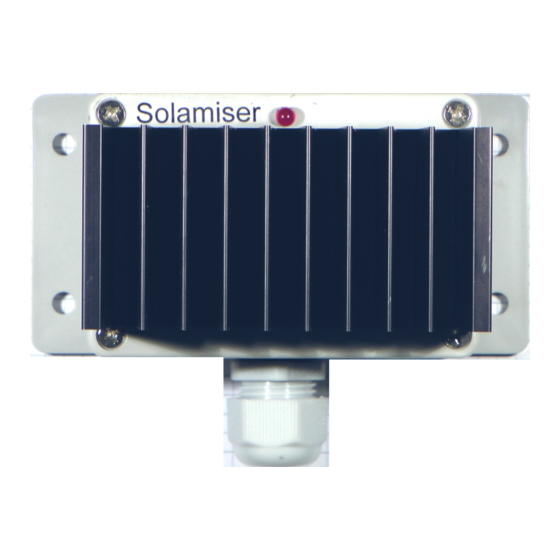
- Page 3 Solamiser User Manual INSTALLATION INSTRUCTIONS Warning: Danger of death due to electric shock. Solamiser is connected directly to the mains consumer unit and should be installed by a qualified electrician in accordance with IEE wiring regulations. Status LED Access Screws...
- Page 4 Solamiser User Manual MOUNTING SOLAMISER a) Using the 4 Fixing holes and screws provided, Install Solamiser on a vertical surface as close as possible to the mains consumer unit. b) Ensure that there is at least 150 mm of clearance...
- Page 5 Solamiser User Manual CONNECTING SOLAMISER A single five core 1.5 mm² flexible cable should be connected to the unit as shown. Depending on the type of 5 core cable used it will either be colour coded or have core numbers.
- Page 6 Solamiser User Manual a) Pass the five core cable through the gland at the bottom of Solamiser and connect to the four way terminal block on the printed circuit board as shown.
- Page 7 Solamiser User Manual b) Using a suitable 3 mm diameter eye crimp connection, connect the separate earth screw (Heatsink mounting screw) to the yellow and green earth core of the 5 core cable. Be careful not to over tighten this screw as it is very easy to crack the ABS plastic lid.
- Page 8 Solamiser User Manual c) Position the PCB copper side facing you with the connector at the top. Ensure the jack socket is protruding into its hole at the left hand side of the wall fixed base.
- Page 9 Solamiser User Manual d) Replace the lid and screw it into position. Note: For safety reasons ensure the lid is securely closed before connecting to the consumer unit.
- Page 10 Solamiser User Manual CONNECTING THE COMSUMER UNIT With its main switch turned OFF remove the front cover of the consumer unit. Refer to the diagram on the next page. e) Identify and disconnect the immersion heater's L (Line) cable from its circuit breaker.
- Page 11 Solamiser User Manual...
- Page 12 Solamiser User Manual Note: Solamiser does not have an internal fuse or circuit breaker as circuit protection is provided by the consumer unit's immersion heater circuit breaker. The rating of this circuit breaker should not exceed 16 A. f) Connect the brown core of the five core cable...
- Page 13 MCB also protects this circuit through Solamiser. This load should not exceed 16A k) If you want Solamiser to remain on immersion all day long, please exchange this unit for the special single channel version of Solamiser. Do not wire H1 and H2 together as this will damage the unit.
- Page 14 Thermostat Immersion + E Solamiser n) If you wish to be able to bypass Solamiser to provide power to your emersion heater to either boost heating or provide heat during the winter if your gas boiler breaks down, you can fit a switch as shown above.
- Page 15 To get the current clamp the right way round proceed as follows: a) Plug the current clamp's 3.5mm Jack plug into the Jack socket on the left hand side of Solamiser. It is safer to plug in the current clamp before clipping round the mains cable.
- Page 16 Turn on the consumer unit immersion heater circuit breaker and ensure that any other switches in the immersion heater circuit are also switched e) The LED at the top of Solamiser should start to blink. f) If the LED is flashing short pulses (0.1 sec ON...
- Page 17 LED a second time. k) If Solamiser's LED is now flashing as described in f) above it is most likely that the current clamp is now in the correct orientation.
- Page 18 LED to flash once per second (on for half a second then off for half a second) indicating energy import. If it flashes once every 2 seconds then the current clamp should be reversed. n) Solamiser is now correctly commissioned.
- Page 19 MODE 1 - IMPORT When the LED flashes ON for half a second then OFF for half a second, Solamiser is detecting import energy. This typically occur after dark. When you are consuming electricity from the grid. The immersion heater is always switched off in MODE 1.
- Page 20 TV. If the sun goes behind a cloud Solamiser will reduce power to the immersion heater to maintain balance. The pulse rate of the LED in MODE 3 reflects the amount of energy being diverted to the immersion heater i.e.
- Page 21 Solamiser User Manual MODE 4 – DIVERTING TO OPTIONAL SECOND LOAD When producing double pulses Solamiser is diverting to an optional second load e.g. a storage heater. The purpose of the double pulse is to indicate that the second load is now connected and the immersion heating cycle has finished.
- Page 22 If the LED flashes in MODE 1 only at all times you may have a faulty immersion. If the LED flashes in MODE 2 only at all times Solamiser is either incorrectly installed or faulty and your immersion may be consuming import energy at a cost.
- Page 23 Solamiser User Manual SPECIFICATIONS Rated Voltage 240V a.c. Rated Current 16A rms. Rated Frequency 50 Hz. Maximum Mains Cable Current through Current Clamp: 100A rms. Maximum Load Current 16A rms per load. Maximum Ambient Temperature 40 Deg C. Power balance point fixed at -5% i.e. exporting approx 150W to avoid import.
Need help?
Do you have a question about the solar panel and is the answer not in the manual?
Questions and answers