
Summary of Contents for Alpermann+Velte RUBIDIUM
-
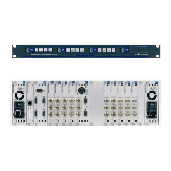
Page 1: The Rubidium Frames Rubidium Series
Installation & Systems Manual Version: 4.1 September 26, 2012 RUBIDIUM SERIES Universal Video Data Processor... -
Page 3: Table Of Contents
Installation & Systems Manual RUBIDIUM SERIES Page 3 CONTENTS REVISION HISTORY COPYRIGHT WARRANTY UNPACKING/SHIPPING/REPACKAGING INFORMATION SAFETY INSTRUCTIONS EC DECLARATION OF CONFORMITY INTRODUCING THE RUBIDIUM SERIES OVERVIEW CONFIGURATION OF THE MODULES: THE PC CONNECTOR SYSTEM EXTENSIONS: THE RLC CONNECTOR AND FURTHER INTERFACES 1.3.1... - Page 4 Installation & Systems Manual RUBIDIUM SERIES Page 4 MODULES OF THE SYSTEM PS: 60 W POWER SUPPLY OF RUBIDIUM SERIES 1 PT: 60 W POWER SUPPLY OF RUBIDIUM SERIES 3 PQ: 60 W POWER SUPPLY WITH OLED DISPLAY PD: POWER DISTRIBUTION...
- Page 5 Installation & Systems Manual RUBIDIUM SERIES Page 5 SOFTWARE TOOLS FOR RUBIDIUM SERIES THE RUBIDIUM CONFIGURATION PC PROGRAM 4.1.1 Overview 4.1.2 Installation 4.1.3 Connection to RUBIDIUM SERIES Chassis 4.1.4 Starting the Program 4.1.5 Overview of Tab Functions 4.1.6 Store a Set-Up to a File, Load and Update the Set-Up of a Module 4.1.7...
-
Page 6: A1 Revision History
July 06, 2012 D1: revised. HT/HV: discontinued. IRIG-B 03: removed. New: Q1, XT/XV, GLS 10 MHz, SB. Completely revised. September 26, 2012 New chapter: RUBIDIUM SERIES 3 – Exchange a Fan. New hardware version DT/DV: version 3. New LTC output gain specifications. -
Page 7: A2 Copyright
Page 7 Copyright Copyright © Alpermann+Velte Electronic Engineering GmbH 2002. All rights reserved. No part of this publication may be reproduced, translated into another language, stored in a retrieval system, or transmitted, in any form or by any means, electronic, mechanical, photocopying, recording, or otherwise without the prior written consent of Alpermann+Velte Electronic Engineering GmbH. -
Page 8: A3 Warranty
This warranty is given by Alpermann+Velte with respect to this product in lieu of any other warranties, express or implied. Alpermann+Velte and its vendors disclaim any implied warranties of merchantability or fitness for a particular purpose. -
Page 9: A4 Unpacking/Shipping/Repackaging Information
Alpermann+Velte dealer. Ensure that all packaging material is removed from the product and its associated components before installing the unit. Products returned to Alpermann+Velte for servicing or repair should have a tag attached showing: Name and complete address of the owner and the name of the person that can be contacted. -
Page 10: A5 Safety Instructions
A5 Safety Instructions The general safety information in this part is for both operating and service personnel. Alpermann+Velte products are only to be used as directed. Specific warnings and cautions will be found throughout the manual where they apply. Review the following safety instructions to avoid injury and prevent damage to this product or any products connected to it. - Page 11 Installation & Systems Manual RUBIDIUM SERIES Page 11 Injury Precautions One or more Power Supply module(s) may be present within this product’s frame, in that case observe the following precautions: WARNING: To prevent fire or shock hazard, do not expose the unit to rain or moisture.
- Page 12 Installation & Systems Manual RUBIDIUM SERIES Page 12 Observe the following general precautions irrespective of the number or kind of modules plugged to the frame: DO NOT OPERATE WITHOUT COVERS To avoid electrical shock or fire hazard, do not operate this product with covers or panels removed.
- Page 13 Installation & Systems Manual RUBIDIUM SERIES Page 13 SUSPECTED FAILURES Whenever it is likely that safe operation is impaired, the apparatus must be made inoperative and secured against unintended operation. The appropriate service authority must then be informed. Do not operate with suspected failures.
- Page 14 Installation & Systems Manual RUBIDIUM SERIES Page 14 Electro Static Discharge (ESD) Precautions All semiconductor devices are sensitive to ESD. To prevent any damage or degradation on components of the product caused by ESD, observe these precautions when directed to do so (installing, removing sensitive components): 1.
-
Page 15: A6 Ec Declaration Of Conformity
Installation & Systems Manual RUBIDIUM SERIES Page 15 A6 EC Declaration of Conformity... -
Page 16: Introducing The Rubidium Series
Installation & Systems Manual RUBIDIUM SERIES Page 16 Introducing the RUBIDIUM SERIES 1.1 Overview RUBIDIUM SERIES is a modular system which offers flexibility to its users. Various rack mount frames are available. On principle, a distinction is made between 1RU (RUB1) and 3RU (RUB3). ... -
Page 17: Configuration Of The Modules: The Pc Connector
Chapter “The RUBIDIUM CONFIGURATION PC Program” gives a short overview of the wide range of options to set up a module. Details to the features of a single module are given in the description of the individual module. -
Page 18: System Extensions: The Rlc Connector And Further Interfaces
Installation & Systems Manual RUBIDIUM SERIES Page 18 1.3 System Extensions: The RLC Connector and Further Interfaces ADR = 1 ADR = 2 ADR = 3 ADR = 4 Ethernet OPER OPER Network OPER OPER SIGNAL SIGNAL SIGNAL SIGNAL ERROR... -
Page 19: The Fail Signals: Error Detecting
Having a frame with at least one power supply module, this pin can be used to supply voltage to another frame. In this case no external voltage output of a Non-Rubidium power supply should be connected at this pin. See specifications of the power supply module if this pin is used as a voltage supply output. -
Page 20: Module And System Configuration
The hard-wired address alone is not sufficient to uniquely identify a module in a system consisting of more than one frame. The RUBIDIUM SERIES HTTP Server additionally offers to identify a frame by a number (1 to 31). A module than can be accessed having the right frame and the right place within the frame selected. -
Page 21: Installation Of A Module
1.4.4 Update Most of the RUBIDIUM SERIES modules can easily get a new firmware by flash programming. The software to do this flash programming is part of the PC program “RUBIDIUM CONFIGU- RATION“. A .tcf file will be supplied/available if it becomes necessary to update a module. -
Page 22: The "Rub1 S1" And "Rub1 T1" Chassis
Page 22 The Rubidium Frames 2.1 RUBIDIUM SERIES 1 Modules belonging to RUBIDIUM SERIES 1 are denoted as RUB1 modules. 2.1.1 The “RUB1 S1” and “RUB1 T1” Chassis The RUB1 S1 chassis was designed to house one rear loading RUB1 module in 19”/1RU space. - Page 23 0.6 kg approx. Dimensions 143 (W) x 44.5 (H) x 180 (D, without DSUBs) mm 5.63 x 1.75 x 7.09 inch Operating voltage and 12 – 30 VDC (for standard Rubidium modules), Operating current 1 A maximum Maximum power 6.5 W...
-
Page 24: The "Rub1 H1" Frame
446.5 (W) x 44.5 (H) x 176.5 (D, without DSUBs) mm (without 19“ front plate) 17.58 x 1.75 x 6.95 inch Operating voltage 12 – 30 VDC (for standard Rubidium modules), nominal 24 VDC Power consumption 2 W (fan and fan module, without further Rubidium modules) Maximum power... -
Page 25: The "Rub1 D1" Frame
Installation & Systems Manual RUBIDIUM SERIES Page 25 2.1.3 The “RUB1 D1” Frame The RUB1 D1 is a rack mount frame in 19”/1RU space. It has an integrated power supply, an 8-digit LED display at the front, and an XLR-DSUB-RJ45 adapter for LTC signals at the rear. - Page 26 This module is part of the delivery and fits into the appropriate double-wide slot. There is no initial set-up or configuration of this module possible; it is not addressable via any Rubidium configuration tool. The serial number is located on the bottom side of the circuit board of this module.
-
Page 27: The "Rub1 Q1" Frame
Installation & Systems Manual RUBIDIUM SERIES Page 27 2.1.4 The “RUB1 Q1” Frame The RUB1 Q1 is a rack mount frame in 19”/1RU space with an 8-digit display. Chassis The RUB1 Q1 mount frame was designed to house up to two additional rear loading RUB1 modules in 1RU space. - Page 28 This module is part of the delivery and fits into the appropriate double-wide slot. There is no initial set-up or configuration of this module possible; it is not addressable via any Rubidium configuration tool. The serial number is located on the bottom side of the circuit board of this module.
-
Page 29: Plug-In A Module
Installation & Systems Manual RUBIDIUM SERIES Page 29 2.1.5 Plug-In a Module All modules of RUBIDIUM SERIES can be “hot swapped”. To plug-in a module please proceed as follows: Remove the solid rear panel cover plate for the slot where the module should be... -
Page 30: Remove A Module
2.1.6 Remove a Module All modules of RUBIDIUM SERIES can be “hot swapped”. There may be occasions when you must exchange a module which has a user defined configuration. If the new module should work with the same application it would be helpful to have the current configuration stored on your PC (see saving a configuration to disk in Windows help program). -
Page 31: The Fan Module: Fan, Frame Address, Tc_Link Termination
Installation & Systems Manual RUBIDIUM SERIES Page 31 2.1.7 The Fan Module: Fan, Frame Address, TC_link Termination RUB1 H1 and RUB1 Q1 frames have a fan module integrated. It is located at one side of the frame behind the DSUB PC connector. There may be occasions when you must exchange this... -
Page 32: The "Rub3 H3" Frame
Installation & Systems Manual RUBIDIUM SERIES Page 32 2.2 RUBIDIUM SERIES 3 Modules belonging to RUBIDIUM SERIES 3 are denoted as RUB3 modules. 2.2.1 The “RUB3 H3” Frame The RUB3 H3 mount frame provides capacity for 21 slots in 19”/3RU space. Some RUB3 modules require two slots (as AT, DT, GT, VD, PT …), other modules one slot (as AV, DV). -
Page 33: Plug-In A Module
Page 33 2.2.2 Plug-In a Module All modules of RUBIDIUM SERIES can be “hot swapped”. To plug-in a module, please pro- ceed as follows: Remove the solid rear panel cover plate for the slot where the module should be installed: Unscrew both the collar screws, so that the rear panel cover plate can be easily removed. -
Page 34: Remove A Module
2.2.3 Remove a Module All modules of RUBIDIUM SERIES can be “hot swapped”. There may be occasions when you must exchange a module which has a user defined configuration. If the new module should work with the same application it would be helpful to have the current configuration stored on your PC (see saving a configuration to disk in Windows help program). -
Page 35: The Rc Module: Fan Control, Frame Address, Tc_Link Termination
Installation & Systems Manual RUBIDIUM SERIES Page 35 2.2.4 The RC Module: Fan Control, Frame Address, TC_link Termination The RUB3 H3 standard frame will be equipped with a RC module. This module contains the fan control electronic, a fail relay for error detection, a fourfold dip switch and a rotary switch. -
Page 36: Modules Of The System
Page 36 Modules of the System 3.1 PS: 60 W Power Supply of RUBIDIUM SERIES 1 This module provides power for all the modules in an RUB1 frame. It can be installed at any slot (location) of the frame just as any other module would. Power is distributed in parallel to all slots and to the 24V pin at the DSUB female connector RLC at the rear of the frame. -
Page 37: Pt: 60 W Power Supply Of Rubidium Series
Installation & Systems Manual RUBIDIUM SERIES Page 37 3.2 PT: 60 W Power Supply of RUBIDIUM SERIES 3 This module provides power for all the modules in an RUB3 frame. It can be installed at any slot (location) of the frame just as any other module would. Power is distributed in parallel to all slots and to the 24V pin at the DSUB female connectors RLC at the RC module. -
Page 38: Pq: 60 W Power Supply With Oled Display
Installation & Systems Manual RUBIDIUM SERIES Page 38 3.3 PQ: 60 W Power Supply with OLED Display RUB1 frames only. This module consists of two physical parts: As a power supply it provides the power for all the modules in the frame, as a Time Code reader it visibly displays the decoded time and user or date data. -
Page 39: Pd: Power Distribution
External units can get its DC power using the terminal blocks; RUBIDIUM SERIES frames use the DSUB connector RLC 1 or RLC 2. The RLC pinning of a RUBIDIUM SERIES frame combines DC, RS485 (= TC_link) and FAIL signals. The RS485/FAIL connector at the rear of PD separates the RS485 (TC_link) and FAIL signals of the RLC1/RLC2 connectors. -
Page 40: At: Analogue Video Time Code
Installation & Systems Manual RUBIDIUM SERIES Page 40 3.5 AT: Analogue Video Time Code The hardware consists of an analogue video channel, time code in/outputs, serial interfaces, as well as some general purpose interfaces (GPI) which may be used for various applications. -
Page 41: Av: Analogue Video
Installation & Systems Manual RUBIDIUM SERIES Page 41 3.6 AV: Analogue Video The hardware consists of an analogue video channel with character inserter and VITC reader/generator. Connections at AV module – version 1 Connections at AV module – version 2... -
Page 42: At/Av Standard Options
Installation & Systems Manual RUBIDIUM SERIES Page 42 3.7 AT/AV Standard Options You will find detailed information in the operating manuals mentioned below. All manuals are available at: http://www.alpermann-velte.com/serv_e/bal_e/bal_e.html. Option Description -B: Video bypass relay The bypass relay appears in the video input to output path, not in the video loop path. -
Page 43: Ai: Analogue Video For Special Applications
Installation & Systems Manual RUBIDIUM SERIES Page 43 3.8 AI: Analogue Video for Special Applications The hardware of these modules comprises serial interfaces (RS232, RS422, RS485), 4 x GPIO, and an analogue video channel. An option has to be selected to give functionality to the module. It is not possible to order this module without an option. -
Page 44: Dt: Digital Video Time Code
Installation & Systems Manual RUBIDIUM SERIES Page 44 3.9 DT: Digital Video Time Code The hardware consists of a digital video channel (SD), time code in/outputs, serial interfaces, as well as some general purpose interfaces (GPI) which may be used for various applications. -
Page 45: Dv: Digital Video
Installation & Systems Manual RUBIDIUM SERIES Page 45 3.10 DV: Digital Video Digital video channel (SD) with character inserter and D-VITC/ATC time code reader and generator. Connections at RUB DV – hardware version 1 Connections at RUB DV – hardware version 2/3... -
Page 46: Dt/Dv Standard Options
Installation & Systems Manual RUBIDIUM SERIES Page 46 3.11 DT/DV Standard Options You will find detailed information in the operating manuals mentioned below. All manuals are available at: http://www.alpermann-velte.com/serv_e/bal_e/bal_e.html. Option Description -B: Video bypass relay The bypass relay appears in the video input to output path, not in the video loop path. -
Page 47: Di: Digital Video For Special Applications
Installation & Systems Manual RUBIDIUM SERIES Page 47 3.12 DI: Digital Video for Special Applications The hardware of these modules comprises serial interfaces (RS232, RS422, RS485), 4 x GPIO, and a digital video channel (SD). An option has to be selected to give functionality to the module. It is not possible to order this module without an option. -
Page 48: Ht: Hd/Sd Video Data And Time Code (Discont.)
Installation & Systems Manual RUBIDIUM SERIES Page 48 3.13 HT: HD/SD Video Data and Time Code (discont.) The hardware consists of a digital video channel (HD/SD), time code in/outputs, serial inter- faces, as well as some general purpose interfaces which may be used for various applications. -
Page 49: Hv: Hd/Sd Video Data (Discont.)
Installation & Systems Manual RUBIDIUM SERIES Page 49 3.14 HV: HD/SD Video Data (discont.) The hardware consists of a digital video channel (HD/SD) with character inserter and D- VITC/ATC time code reader and generator. VIDEO IN LOOP OUT VIDEO OUT... -
Page 50: Xt: 3G/Hd/Sd Video Data And Time Code
Installation & Systems Manual RUBIDIUM SERIES Page 50 3.15 XT: 3G/HD/SD Video Data and Time Code The hardware consists of a digital video channel (3G/HD/SD), time code in/outputs, serial interfaces, as well as general purpose interfaces which may be used for various applications. -
Page 51: Xv: 3G/Hd/Sd Video Data
Installation & Systems Manual RUBIDIUM SERIES Page 51 3.16 XV: 3G/HD/SD Video Data The hardware consists of a digital video channel (3G/HD/SD) with character inserter and D- VITC/ATC time code reader and generator. VIDEO IN LOOP OUT VIDEO OUT Alpermann+Velte... -
Page 52: Xt/Xv Standard Options
Installation & Systems Manual RUBIDIUM SERIES Page 52 3.17 XT/XV Standard Options You will find detailed information in the operating manuals mentioned below. All manuals are available at: http://www.alpermann-velte.com/serv_e/bal_e/bal_e.html. Option Description -B: Video bypass relay The bypass relay appears in the video input to output path, not in the video loop path. -
Page 53: Xi: Digital Video For Special Applications
Installation & Systems Manual RUBIDIUM SERIES Page 53 3.18 XI: Digital Video for Special Applications The hardware of these modules comprises serial interfaces (RS232, RS422, RS485), 4 x GPIO, and a digital video channel (SD/HD/3G). An option has to be selected to give functionality to the module. It is not possible to order this module without an option. -
Page 54: Gt: Master Time Code Generator
Installation & Systems Manual RUBIDIUM SERIES Page 54 3.19 GT: Master Time Code Generator The hardware consists of an analogue video channel, time code in/outputs, time and date reference in/outputs as well as some general purpose interfaces (GPI), which may be used for various applications. -
Page 55: Gi: Master Irig-B Generator
Installation & Systems Manual RUBIDIUM SERIES Page 55 3.20 GI: Master IRIG-B Generator The hardware consists of an IRIG-B generator, time and date reference in/outputs as well as some general purpose interfaces (GPI), which may be used for various applications. The module outputs various real-time signals: IRIG-B, impulse time telegram, time and date serial data string. -
Page 56: Gl: Ltc(Mtd) Generator
Installation & Systems Manual RUBIDIUM SERIES Page 56 3.21 GL: LTC(MTD) Generator The hardware consists of an analogue video channel, time code in/outputs, time and date reference in/outputs as well as some general purpose interfaces (GPI), which may be used for various applications. -
Page 57: Gt/Gi/Gl: Standard Options
-M: Impulse telegram With this option a built-in distribution amplifier supplies the output to control analogue clocks of the Alpermann+Velte system with power as well analogue clocks as with time data. The time data forms a telegram similar to the German radio time telegram DCF77. -
Page 58: Gw: Master Word Clock Generator
Installation & Systems Manual RUBIDIUM SERIES Page 58 3.23 GW: Master Word Clock Generator The hardware consists of four word clock outputs, a SYNC input for video or 10 MHz synchronisation, time and date reference in/outputs, as well as some general purpose interfaces (GPIO), which may be used for various applications. -
Page 59: Gb: Master Black Burst Generator
Installation & Systems Manual RUBIDIUM SERIES Page 59 3.24 GB: Master Black Burst Generator The hardware consists of two black burst outputs, a SYNC input for video or 10 MHz synchronisation, time and date reference in/outputs, as well as some general purpose interfaces (GPI), which may be used for various applications. -
Page 60: Vd: Distribution Amplifier
Installation & Systems Manual RUBIDIUM SERIES Page 60 3.25 VD: Distribution Amplifier The module is a distribution and amplifier for signals which - for example - are output signals of the MTD connector of the GT module. OUT_2 Alpermann+Velte OUT_1... -
Page 61: Vi: Ltc Or Irig Distribution Amplifier
Installation & Systems Manual RUBIDIUM SERIES Page 61 3.26 VI: LTC or IRIG Distribution Amplifier This module distributes and amplifies one input to six LTC (EBU/SMPTE) or IRIG time code outputs. A seventh spare output stage together with a change-over relay at each of the six outputs enables complete redundant output signals. -
Page 62: Vm: Continuous Wave Distribution Amplifier
Installation & Systems Manual RUBIDIUM SERIES Page 62 3.27 VM: Continuous Wave Distribution Amplifier This module distributes and amplifies one continuous wave input to six outputs. A seventh spare output stage together with a change-over relay at each of the six outputs enables complete redundant output signals. -
Page 63: Vl: Ltc Distribution And Converter Module
For example the Alpermann+Velte LTC(MTD) can be decoded and converted to various output formats, so that external devices can display the individual stop timers or time zone data. Impulse telegram outputs are available to control Alpermann+Velte analogue clocks. -
Page 64: Vt: Telegram Distribution Amplifier
This module is a distribution and amplifier for a time telegram signal used to control Alpermann+Velte analogue slave clocks with a 2-wire interface. Two output stages are available, each current limited to 800 mA. A maximum of 80 slave clocks of type “MTD Clock”... -
Page 65: Ie: Interface Ethernet
Page 65 3.30 IE: Interface Ethernet The Alpermann+Velte Rubidium series “IE” module is a stand alone Ethernet “mini server”. This unit makes an access to all connected “RUB” modules possible (via our internal bus connections “TC_link”), thus enabling a configuration of the modules as well as to open a status monitor. -
Page 66: Gps 10 Mhz: Gps Satellite Receiver
Installation & Systems Manual RUBIDIUM SERIES Page 66 3.31 GPS 10 MHz: GPS Satellite Receiver This module generates GPS disciplined frequencies and a time & date reference. It is an ideal solution for synchronization tasks. Alpermann+Velte ANTENNA PC / GPI B... -
Page 67: Gls 10 Mhz: Glonass/Gps Satellite Receiver
Installation & Systems Manual RUBIDIUM SERIES Page 67 3.32 GLS 10 MHz: GLONASS/GPS Satellite Receiver This is a combined GLONASS/GPS receiver. This module generates frequencies and time & date reference signals disciplined by the satellites. It is an ideal solution for synchronization tasks. -
Page 68: Sl: Ltc Monitoring And Changeover Unit
Installation & Systems Manual RUBIDIUM SERIES Page 68 3.33 SL: LTC Monitoring and Changeover Unit This module can frame accurate and in real-time compare and contrast two incoming LTCs for indescribable differences. In the event of a failure, “SL” automatically switches to the other faultless source. -
Page 69: Sv: Vitc Monitoring And Changeover Unit
Installation & Systems Manual RUBIDIUM SERIES Page 69 3.34 SV: VITC Monitoring and Changeover Unit This module can frame accurate and in real-time compare and contrast two incoming VITCs for indescribable differences. In the event of a failure, “SV” automatically switches to the other faultless source. -
Page 70: Sr: Reference Monitoring And Changeover Unit
Installation & Systems Manual RUBIDIUM SERIES Page 70 3.35 SR: Reference Monitoring and Changeover Unit This module can compare and contrast two incoming reference signals for indescribable differences. In the event of a failure, “SR” automatically switches to the other faultless source. -
Page 71: Si: Irig Monitoring And Changeover Unit
Installation & Systems Manual RUBIDIUM SERIES Page 71 3.36 SI: IRIG Monitoring and Changeover Unit This module can frame accurate and in real-time compare and contrast two incoming IRIG time code signals for indescribable differences. In the event of a failure, “SI” automatically switches to the other faultless source. -
Page 72: Sw: Word Clock Monitoring And Changeover Unit
Installation & Systems Manual RUBIDIUM SERIES Page 72 3.37 SW: Word Clock Monitoring and Changeover Unit This module can supervise and analyse incoming Word Clock signals of two sources. Each source can deliver up to four different Word Clock signals. In the event of a failure of one source, “SW”... -
Page 73: Sb: Analogue Video Monitoring And Changeover
Installation & Systems Manual RUBIDIUM SERIES Page 73 3.38 SB: Analogue Video Monitoring and Changeover SB monitors and analyses two sources of video sync signals. Each source can deliver one signal or two signals of type black burst or tri-level, even with mixed types. If a signal contains VITC, this time code will be monitored and analysed as well. -
Page 74: Software Tools For Rubidium Series
USB Driver for Rubidium and TCU Please copy and extract this software on your computer – maybe into a RUBIDIUM directory. If the PC interface at the Rubidium chassis uses the USB standard, please proceed as follows for your first installation: ... -
Page 75: Connection To Rubidium Series Chassis
Connection to RUBIDIUM SERIES Chassis The RUBIDIUM CONFIGURATION program uses either a RS232 serial interface or a USB interface in order to communicate with a module. The PC connector at the Rubidium chassis determines the kind of this interface. RS232... -
Page 76: Starting The Program
The recently selected port will be shown. If this does not match the port to which the Rubidium housing is connected to, you have to select the port. Opening the drop-down list will list all ports which are available. Likewise it is possible to manually type in a port description. -
Page 77: Overview Of Tab Functions
4.1.5 Overview of Tab Functions The program RUBIDIUM CONFIGURATION works with tab cards. With one click on button Configure all those tabs will be displayed which are presently enabled for the selected module. Click on the Functions tab to see all available tabs in a list. At the “Functions” tab, you can enable and disable all tabs which are available for the selected module. -
Page 78: Store A Set-Up To A File, Load And Update The Set-Up Of A Module
Button Save or select Save or Save as... at the “File” menu: Store the set-up as it is presented by the RUBIDIUM CONFIGURATION PC program to a new file (“Save as...”) or to an existing file (“Save”) at your PC. This may be helpful because ... -
Page 79: The "Profile" Tab: Store And Load A Complete Set-Up On The Module
Installation & Systems Manual RUBIDIUM SERIES Page 79 4.1.7 The “Profile” Tab: Store and Load a Complete Set-Up on the Module Standard modules have a flash memory to store different set-ups. A complete set-up stored to the module is called a “profile”. You can identify different profiles by a number or a name. If a module has one or more keys or GPI programmed with “Load Profile“... -
Page 80: The "System" Tab: Module Identification, Reset, Snmp, Fan Control
Installation & Systems Manual RUBIDIUM SERIES Page 80 4.1.8 The “System” Tab: Module Identification, Reset, SNMP, Fan Control Unit Name The connected module can get a name. You may enter, change or verify this name at this window. After a change press the tabulator key at the PC’s keyboard. - Page 81 Installation & Systems Manual RUBIDIUM SERIES Page 81 Info Displays module’s status information: type of module, firmware versions, options - if there is any installed. SNMP Trap Enable Click “Any Trap” to enable the SNMP feature. If this check box is not activated, no SNMP trap will be generated.
-
Page 82: The Rubidium Series Http Server
4.2.1 Overview, Connecting the IE Module The RUBIDIUM SERIES HTTP server was developed so that users have a uniform and easy set- up of all configurable hardware modules. The HTTP server is located in the IE module and can be accessed via 10/100base-T Ethernet and a web-browser. -
Page 83: Ip Configuration
If you have a firewall running, please disable it or make the UDP port 8001 available for incoming and outgoing traffic. The Rubidium Config program is part of the delivery or available at: http://www.alpermann-velte.com/serv_e/software_e/software_e.html. -
Page 84: The Rubidium Homepage
Page 84 4.2.3 The Rubidium Homepage To open the RUBIDIUM homepage, start an Internet Browser and type in the IP address of the IE module in the location bar. Place a direct link on your PC desktop to have an easy access to the RUBIDIUM SERIES system. -
Page 85: Accessing A Configurable Module
Installation & Systems Manual RUBIDIUM SERIES Page 85 4.2.5 Accessing a Configurable Module Click on “Configuration“ at the RUBIDIUM homepage to open the Configuration page. step: Drop-down list Frame: select the frame number. Please notice chapter “Identification of Modules in a RUBIDIUM System”. -
Page 86: The "Functions" Page
Installation & Systems Manual RUBIDIUM SERIES Page 86 4.2.6 The “Functions“ Page As soon as a communication to a single module has been established, the Configuration page gives a list of all the links which correspond to all the currently available or used pages of this specific module. -
Page 87: The "Profile" Page: Store And Load Set-Ups On The Module Or On The Pc
Installation & Systems Manual RUBIDIUM SERIES Page 87 4.2.7 The “Profile“ Page: Store and Load Set-Ups on the Module or on the PC Standard modules have a flash memory to store different set-ups. A complete set-up stored to the module is called a “profile”. You can identify different profiles by a number or a name. If a module has one or more keys or GPI programmed with “Load Profile“... - Page 88 Installation & Systems Manual RUBIDIUM SERIES Page 88 Load Profile Profile Select a number or a name from the drop-down list, then click on the “Load Profile“ button to load the profile. This will interrupt the operating mode of the module. The current set-up of the module will be replaced.
-
Page 89: The "System" Page: Module Identification, Reset, Snmp, Fan Control
Installation & Systems Manual RUBIDIUM SERIES Page 89 4.2.8 The “System“ Page: Module Identification, Reset, SNMP, Fan Control Unit: The connected module can get a name. You may enter, change or verify this name at the “Name” entry. After a change click on button Save To Module to transfer the new name to the module. -
Page 90: The Status Monitor
4.3.1 Status Monitor by IE Module The RUBIDIUM SERIES HTTP server, located in the Rub IE module, offers a status monitor for all configurable modules. Please refer to the chapter “The RUBIDIUM SERIERS HTTP Server” for a detailed description of how to access the RUBIDIUM SERIES system and how to open the RUBIDIUM homepage. -
Page 91: Status Monitor By Pc Program
Page 91 4.3.2 Status Monitor by PC Program The PC program RubStatSE.exe uses the PC interface (RS232 or USB) of the RUBIDIUM housing. This program is part of the “Rubidium Configuration and Status Monitor PC Programs” packet you can download at: http://www.alpermann-velte.com/serv_e/software_e/software_e.html. -
Page 92: Status Of Fans And Power Supplies
This monitoring feature has to be switched on: Click on the ‘Fan monitoring’ check box of the ‘System” function utilizing one of the Rubidium configuration tools: If more than one module has “Fan Monitoring” enabled, there will be only one module which indeed is responsible for monitoring.
Need help?
Do you have a question about the RUBIDIUM and is the answer not in the manual?
Questions and answers