Table of Contents
Advertisement
Advertisement
Table of Contents

Related Manuals for JEM AF-1

Summary of Contents for JEM AF-1
- Page 1 AF-1 and AF-2 fans user manual...
- Page 2 AF-1 AF-2 ©2005-2007 JEM / Martin Professional A/S. All rights reserved. No part of this manual may be reproduced, in any form or by any means, without permission in writing from Martin Professional A/S. Information subject to change without notice. Martin Professional A/S and all affiliated companies disclaim liability for any injury, damage, direct or indirect loss, consequential or economic loss or any other loss occasioned by the use of, inability to use or reliance on the information contained in this manual.
-
Page 3: Table Of Contents
Remote control installation ........11 AF-1 10 V control installation ....... . 12 DMX installation . - Page 4 – DMX in (5-pin XLR) f – DMX out (3-pin XLR) g – DMX in (3-pin XLR) h – DIP switch i – Data LED 1 2 3 5 6 7 8 910 AF-1 and AF-2 fans user manual...
-
Page 5: Introduction
The AF-1 fan can also be controlled using a 0 - 10 V analog controller. The most recent version of this manual is available under Smoke in the Support area of the Martin website at: http://www.martin.com F e a t u r e s •... -
Page 6: Safety Information
The AF-1 can also be controlled singly or on a multiple link using an analog 0 - 10 V controller. S a f e t y i n f o r m a t i o n Warning! This product is not for household use. -
Page 7: Unpacking
• Do not spill fluid over the machine. If fluid is spilled, disconnect the machine from power and clean with a damp cloth. If fluid is spilled onto electronic parts, contact an approved JEM/Martin dealer for advice. • Do not dismantle or attempt to repair a faulty machine. Refer all service to an authorized JEM/Martin service dealer. -
Page 8: Installation
Fans are supplied set up to match local voltage and frequency settings. The factory default setting is shown on the serial number label. Warning! For protection from fire and electric shock, AF-1 and AF-2 fans must be grounded (earthed). The power supply must have overload and ground-fault protection. -
Page 9: Physical Installation
P h y s i c a l i n s t a l l a t i o n The AF-1 fan may be suspended from a suitable support such as a truss, placed on a horizontal surface resting on its rubber feet, or fastened to a surface. - Page 10 AF-1 and AF-2 fans can be installed on a level horizontal surface: • The AF-1 can be placed on a surface resting on its rubber feet. • The AF-2 can be installed in a touring frame (available as an accessory) and then placed on a surface resting on the frame’s rubber feet.
-
Page 11: Installing Control Hardware
DMX using a DMX control device and serial data link. The AF-1 can also be operated using a 0 - 10 volt DC analog control device. Up to four AF-1 fans can be linked in remote and 10 V analog operation. -
Page 12: Control Installation
• The AF-2 fan has both three-pin and five-pin XLR connectors for DMX IN and DMX OUT. All DMX connectors on AF-1 and AF-2 fans are wired with pin 1 to ground, pin 2 to signal - (cold), and pin 3 to signal + (hot). This is the standard pin assignment for DMX devices. - Page 13 To connect to devices with reversed polarity, use a phase-reversing adaptor (P/N 11820006). To connect the AF-1 to a device with a 5-pin output, use a 5-pin male to 3- pin female XLR adaptor cable (P/N 11820005). To connect the AF-1 to a device with a 5-pin input, use a 3-pin male to 5-pin female adaptor cable (P/N 11820004).
- Page 14 The DMX address on AF-1 and AF-2 fans can be set to any channel from 1 to 512 using DIP-switch pins 1 - 10: 1. Decide on an available DMX address for each machine. 2. Look up the DIP-switch settings using the Martin Address Calculator at http://www.martin.dk/service/utilities/AddrCalc/index.asp, or look for...
- Page 15 D M X a d d r e s s D I P - s w i t c h s e t t i n g s To use this table, first find the DMX address in the main block in the table. Then read the settings for pins 1 - 5 to the left and read the settings for pins 6 - 9 above the address.
-
Page 16: Operation
U s i n g f a n s w i t h s m o k e d u c t i n g To avoid residue build-up and preserve smoke quality, connect fans to smoke ducting using a Y-shaped arrangement, placing the fan on one arm of the Y and the smoke machine on the other. AF-1 and AF-2 fans user manual... -
Page 17: Remote Control Operation
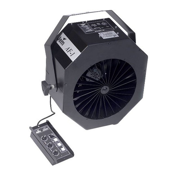
RUN TIME CONTROL – Sets duration of operating periods during timer-controlled operation. The multifunction remote control unit supplied with the AF-1 and AF-2 fans allows instant or timer-controlled fan operation and airflow control. The unit also gives feedback on the status of the machine. -
Page 18: Dmx Control
To extend timer settings, press the X8 button. This will multiply both RUN and DELAY times by 8. D M X c o n t r o l Fan speed on the AF-1 and AF-2 fans can be controlled using a DMX controller. DMX controller op eration When a fan is powered on, the Data LED next to the DIP-switch will light when a valid DMX signal is received. -
Page 19: Service And Maintenance
Use a soft brush and vacuum to clean grills and fan blades. AF-1 cleaning access 1. Disconnect the fan from power. - Page 20 It should be possible to clean the machine without removing the rear grill that holds the fan motor. 4. After cleaning, replace the screws and front grill. Reassemble exactly as shown in the next illustration, making sure that the rubber AF-1 and AF-2 fans user manual...
-
Page 21: Replacing The Main Fuse
The main fuse can be replaced by the user if necessary. An indication that the main fuse may have blown is that the Power LED (on the AF-1 only) or the Data status LED (on AF-1 and AF-2 fans) does not light when: •... -
Page 22: Troubleshooting
Check, and if necessary AF-2: Incorrectly operation reassemble (see “AF-2 assembled grill mounting cleaning access” on hardware page 20) Grills and/or fan blades Check and clean dirty Reduced airflow Low supply voltage Check AC supply AF-1 and AF-2 fans user manual... -
Page 23: Specifications
AF-1 SPECIFICATIONS P h y s i c a l Dimensions (L x W x H) ......320 x 180 x 360 mm (12.6 x 7.1 x 14.2 in.) - Page 24 AF-1 DMX Fan (US model: 110/120V, 50/60 Hz) ... .P/N 92615100 AF-1 DMX Fan (EU model: 220/240 V, 50/60 Hz) ... .P/N 92615000...
-
Page 25: Specifications
C o n t r o l a n d p r o g r a m m i n g JEM Multifunction remote control unit (supplied) DMX control protocol ......USITT DMX-512 (1990) DMX channels . - Page 26 3m (9.8 ft) IEC power cable 18AWG with US male connector (UL approved) User manual JEM multifunction remote control with 5 m (16.4 ft) cable and XLR connector Adjustable flying bracket I n c l u d e d i t e m s ( E U m o d e l ) 2m (6.5 ft) IEC power cable 3 x 1.0mm...
- Page 28 www. martin. com • Olof Palmes Allé 18 • 8200 Aarhus N • Denmark Tel: +45 8740 0000 • Fax +45 8740 0010...
- Page 29 AF-2 specifications...
Need help?
Do you have a question about the AF-1 and is the answer not in the manual?
Questions and answers