Table of Contents
Advertisement
Advertisement
Table of Contents

Summary of Contents for Vent-Axia VAUFHTC
-
Page 2: Table Of Contents
User Manual 1. Product description - Area of use... 2. Technical data......3. -
Page 3: Product Description - Area Of Use
1. PRODUCT DESCRIPTION – AREA OF USE Thermostat for regulating underfloor electric heating cables, temperature range within +5 to +40 °C (default). Ref 446174 is programmable, and regulate the room or floor temperature automatically. The thermostat can operate in two modes, constant temperature mode or event mode. -
Page 4: Technical Data
with an external sensor which should be placed (embedded) into the floor between two heating cable loops, near the floor surface. Temperature can be regulated by the floor sensor or the room sensor. A combination mode is also available where both sensors are used. - Page 5 Maximum load 16A(approx. 3600W at rated voltage) Switch (ON/OFF) Electronic From +5°C to +40°C Temperature range (+41°F to +104°F) (default) Designed working 1-50 °C (Room sensor) temperatures for sensors 1-80 °C (Floor sensor) Dimensions 84x84x40mm(25 mm socket) Encapsulation IP 21 Length floor sensor cable Cross section area,...
-
Page 6: Explanations Of The Symbols In Display
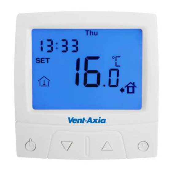
3. EXPLANATION OF SYMBOLS IN DISPLAY Clock (*) Day of week (*) Measured, or set Antifreeze (*) temperature “SET” Heat indication shown. symbol. Room sensor (*) Event/operation mode symbols(*) Floor sensor (*) Shown if override is active Timer (*) Shown when setting events/modes. Shown when adjusting general settings * These symbols are only shown if the function/state is active. - Page 7 The thermostat is in constant temperature mode. If switched to event mode the following predefined program will start running: MONDAY - FRIDAY: Start time for normal operation 06.00 Temperature 21°C (morning) Start time saving 09.00 Temperature 16°C operation Start time for evening operation 17.00 Temperature 21°C Start time for night saving...
-
Page 8: Operation Of The Thermostat
SATURDAY - SUNDAY: Start time for normal operation 08.00 Temperature 21°C (morning) Day saving operation(deactivated -- .-- Temperature -- °C by default) Evening operation(deactivated by -- .-- Temperature -- °C default) Start time night saving 22.00 Temperature 16°C operation For adjusting settings and other operational possibilities please see section 5 and 6. -
Page 9: Constant Temperature Mode
5.1. Constant temperature mode The display will show the sensor in use and the temperature (or the set temperature according to settings, see section 6.1 and sub-setting 12:DF default display). The set temperature can be adjusted by the user by pressing the UP and DOWN buttons. - Page 10 In this mode the display will show the sensor in use, the clock, the current event (in this case "evening operation"), the temperature (or the set temperature according to settings, see section 6.1 and sub-setting 12:DF default display), and the present day (in this case Saturday).
- Page 11 Night saving operation From time D to A For SATURDAY to SUNDAY there are two different events by default (up to four events can be activated): Normal operation (morning) From time E to F Day saving operation (not defined by default) Evening operation (not defined by default) Night saving operation...
-
Page 12: View Measured Sensor Values
5.3. View measured sensor values This function is only available if sub-setting 12:DF = 01, see section 6.2. Further on, you cannot see the measured value of a sensor that is not active, according to sub-setting 10:SE, see section 6.2. Press and hold CLOCK button for 3 seconds to see measured value of floor (external) sensor. -
Page 13: Sub-Settings, Parameters
Sub-setting number Abbrevation for setting Current parameter, which can be adjusted. This is the menu for general settings, containing 12 different sub-settings. Sub-setting 01:CF is shown first. Pressing the CLOCK button lets you cycle between the other 12 different sub-settings. UP and DOWN keys adjust the current parameter as shown in the display. - Page 14 both internal and external sensor. 04:FR Antifreeze function. 00=Off, 01=On. If function is on the antifreeze symbol will be shown in the display. See also sub-setting 05. 05:FS Temperature limitations, antifreeze and maximum floor temperature. 05=Basic antifreeze, the thermostat will start heating if the temperature goes below 5 degree Celsius.
-
Page 15: Event Mode Settings
temperature 08:FL Defines valid minimum setting/value for external/floor temperature. 09:FL Defines valid maximum setting/value for external/floor temperature. 10:SE Sensor selection. 00=Room sensor, 01=Floor sensor, 02=Both, combination mode. Set active sensor(s) according to installation instructions. 11:CL Clock. NO=No clock, thermostat will run in constant temperature mode, 12h=12 hour clock with AM/PM, 24h=24 hour clock without AM/PM displayed. -
Page 16: Event Mode Settings
With the clock activated see section 6.1, you can change the settings for event mode of operation. Press the CLOCK button once and the following will be displayed: You are now adjusting settings for weekdays Monday to Friday, “Normal operation (morning)”. The start-time will be blinking, and it can now be changed with UP and DOWN buttons. -
Page 17: Setting The Clock
Saturday and Sunday is defined the same way. For Saturday and Sunday day saving and evening operation is disabled by default indicated by "- -" symbols. During programming, if no buttons are pressed for 10 seconds settings will be saved and display will return to default display. Pressing ON/OFF button will cancel and return to default display. -
Page 18: Setting The Timer
CLOCK Goes to the next setting (minutes, then finally selection of day) Leave the thermostat for 10 seconds and all adjustments will be saved. Press ON/OFF button to cancel. 6.5. Setting the timer If you want the thermostat active at certain timeframe each day you can use the timer function. -
Page 19: Error Messages
other times it will be off. Set the startup-time equal to the end-time to disable the function. 7. ERROR MESSAGES If there is a fault associated with a sensor either E1 or E2 will be displayed flashing, along with an indication of which sensor is faulty. -
Page 20: Installation Instructions
INSTALLATION INSTRUCTIONS Vent-Axia VAUFHTC Ref 446174 Product description VAUFHTC Ref 446174 is a digital thermostat for controlling electrical underfloor heating cables. The thermostat is equipped with an integrated room sensor and is delivered with an external (floor) sensor. The thermostat shall be mounted in a standard junction box. - Page 21 Vent-Axia offers a 2 year warranty on defects in material and workmanship in the sold product, under proper use and service. In case of a defect, Vent-Axia will repair or replace the product. The warranty does not extend to defects caused by a faulty installation or improper use.
-
Page 22: Before Installing The Thermostat
Before installing the thermostat Determine whether the heated floor shall be controlled by using the room or floor sensor. For guidance, see table 1. Both sensors can be set active. The room sensor will then be the primary sensor, and the floor sensor can function as a temperature limitation sensor, protecting the floor from overheating. - Page 23 Room type Floor Room Recommended sensor sensor heating cable floor products from sensor (limita Vent-Axia tion-se nsor) Concrete floor with tiles, stone or slate, high area load (100 - 150 W/m²) VAUFHC Bathroom VAUFHM100/15 Washroom Toilet Wet rooms in general...
- Page 24 Concrete floor with tiles, stone or vinyl, low to medium area load (60 - 100 W/m²) VAUFHC Living room VAUFHM100/15 Kitchen Hall Sleeping room Living areas in general Concrete floor with parquet or laminate, low to medium area load (60 – 100 W/m²) VAUFHC Living room VAFHM100/150...
- Page 25 1. Installation of the floor sensor 1.1 The floor sensor shall be positioned centered between two heating cable strings in the floor before pouring concrete or screed. It is recommended to install the sensor in a flexible conduit. The conduit should cover the full sensor length.
- Page 26 controlled by using the room sensor, the thermostat must be placed inside the room. 1.6 Separate the frontside (screen) and the backside (socket) by pressing lightly on the top middle (opening mechanism), see fig. 2. Place the screen somewhere safe. 1.7 Connect the heating cable to the connectors 5 and 6 (fig.
- Page 27 the frontside into the tracks at the bottom first, then align the pins so they start going into the slot correctly, then press the entire cover into its' final position. 1.13 See the enclosed user manual for operation, programming of day/night function, clock setting and general setting adjustments Fig.
- Page 28 Fig. 2: Attaching and detaching the frontside (screen) from socket Use Screw Driver to Use Screw Driver to open the plastic housing. open the plastic housing. Slot to align pins into. Slot to align pins into. BE CAREFUL! Pins BE CAREFUL! Pins must go correctly into must go correctly into slot.
- Page 29 SALES ENQUIRIES: Tel: 0844 8560590 Fax: 01293 565169 TECHNICAL SUPPORT: Tel: 0844 8560594 Fax: 01293 539209 For details of the warranty and returns procedure please refer to www.vent-axia.com or write to Vent-Axia Ltd, Fleming Way, Crawley, RH10 9YX 446256A 0111...
Need help?
Do you have a question about the VAUFHTC and is the answer not in the manual?
Questions and answers