Table of Contents
Advertisement
Quick Links
DT- - - - 28
DT
284 4 4 4 4 4 4 4 R R R R
DT
DT
28
28
4 4 4 4 000 COUNTS AUTO
000 COUNTS AUTO- - - - RANGE
000 COUNTS AUTO
000 COUNTS AUTO
AC+DC TRUE- - - - RMS
AC+DC TRUE
AC+DC TRUE
AC+DC TRUE
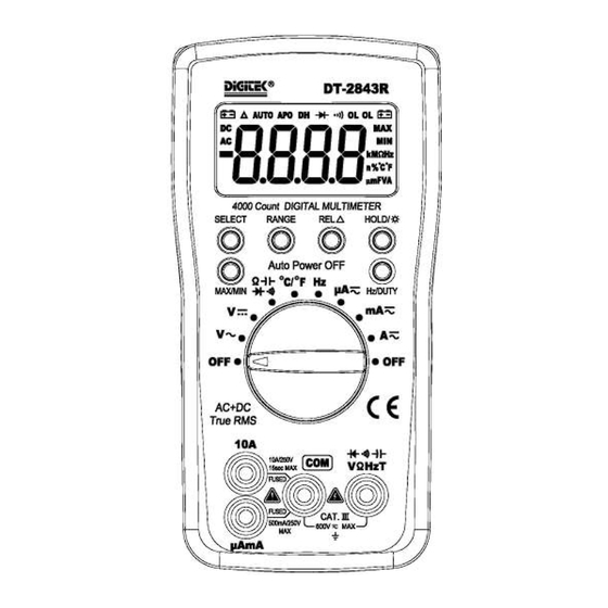
DIGITAL MULTIMETER
DIGITAL MULTIMETER
DIGITAL MULTIMETER
DIGITAL MULTIMETER
OPERATION MANUAL
RANGE
RANGE
RANGE
RMS
RMS
RMS
Advertisement
Table of Contents

Summary of Contents for Digitek DT-2844R
- Page 1 DT- - - - 28 284 4 4 4 4 4 4 4 R R R R 4 4 4 4 000 COUNTS AUTO 000 COUNTS AUTO- - - - RANGE RANGE 000 COUNTS AUTO 000 COUNTS AUTO RANGE RANGE AC+DC TRUE AC+DC TRUE- - - - RMS AC+DC TRUE...
- Page 2 1. ATIONSAFETY INFORM SAFETY SYMBOLS Warning! Dangerous Voltage (Risk of electric shock). Caution! Refer to the user’s manual before using this Meter. Double Insulation. Alternating Current (AC). Direct Current (DC). Either DC or AC. Ground (maximum permitted voltage between terminal and ground). US Safety Standard.
- Page 3 Polarity: Automatic negative polarity indication. Zero adjustment: Automatic. Overrange indication: The “OL” or “-OL” display. Low battery indication: Display " " sign. Data hold: Display “DH” sign. Relative measurement: Display “△” sign. Auto Power Off: Display “APO” sign. When measurement exceeds 10 minutes without switching mode and pressing key, the meter will switch to standby mode.
- Page 4 Overload protection: 0.5A/250V, 10A/250V fuse. [1] 10A for 15sec each 15min maximum. 2.2.4 AC Current ( AC+DC True RMS Range Accuracy ± ([% of Reading] + [Counts]) DC, 45Hz to 2kHz 400 A, 4000 A 2.0%+3 40mA, 400mA 2.0%+3 4A,10A 2.5%+3 Overload protection: 0.5A/250V, 10A/250V fuse.
- Page 5 3. OPERATION 3.1 DC Voltage Measurement 1) Connect the black test lead to "COM" socket and red test lead to the "V Hz" socket. 2) Set the selector switch to desired “V ” position. 3) Measure the voltage by touch the test lead tips to the test circuit where the value of voltage is needed.
-
Page 6: Battery Replacement
forward voltage of this diode. 5) Connect the test leads to two point of circuit, if the resistance is lower than approx. 100 , the buzzer sounds. Note: Make sure the power is cut off and all capacitors need to be discharged under this measurement. - Page 7 1) This meter is provided with a 0.5A/250V fuse to protect the current measuring circuits which measure up to 500mA, with a 10A/250V fuse to protect the 10A range. 2) Ensure the instrument is not connected to any external circuit, set the selector switch to “OFF”...
Need help?
Do you have a question about the DT-2844R and is the answer not in the manual?
Questions and answers