Table of Contents
Advertisement
Advertisement
Table of Contents

Summary of Contents for JL Audio CR-1
- Page 1 Active Subwoofer Crossover Owner’s Manual...
-
Page 2: Important Safety Instructions
10) Cleaning — The device should be cleaned only as recommended in the operating instructions. 11) Nonuse Periods — The power cord of the device should be unplugged from the outlet when the device is left unused for long periods of time. | CR-1 Page 2... - Page 3 Precautions should be taken so that the grounding means of the device are not defeated. Defeating the grounding prong on the device power cord could increase the risk of electric shock and could result in permanent damage to the device’s electronics. | CR-1 Page 3...
-
Page 4: Table Of Contents
INTRODUCTION Thank you for purchasing a JL Audio CR-1 active subwoofer crossover. Your CR-1 has been designed and built in the U.S.A. by a passionate team of audio professionals with vast experience in signal processing and a complete commitment to “ahead of the curve” audio performance. -
Page 5: Product Overview
2-channel audio (via the CR-1’s bass management) and multichannel audio (via your pre-pro or receiver’s bass management). As you can see from this brief introduction, the CR-1 packs a lot of useful technology and functionality. Please read the following sections thoroughly to properly connect and set up your CR-1. -
Page 6: Package Contents And Placement Considerations
CR-1. We also do not recommend placing the CR-1 directly on top of a power amplifier or receiver, as the heat generated by those components could affect the CR-1. -
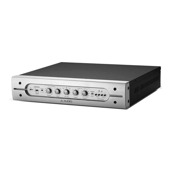
Page 7: Front Control Panel Layout
Ground Lift Stereo Inputs Managed Bass Switch page 12 Inputs page 13 page 12 Fuse page 13 Balanced XLR/TRS Managed Bass Balanced XLR/TRS Managed Bass Input Type Stereo Inputs Inputs Switch page 12 page 12 page 12 | CR-1 Page 7... -
Page 8: Front Panel Controls In Detail
CR-1’s circuitry. The LED next to the power switch is unlit when the power is off. When the CR-1’s power switch is in the “on” ( ) position, the CR-1’s circuitry is activated and the LED next to the power switch will light up GREEN. - Page 9 Crossover Slope Switch The “Crossover Slope” switch changes the attenuation slope of the high-pass and low-pass filters. CR-1 offers a choice between a moderate 12 dB/octave (2nd order) and a steep 24 dB/octave (4th order) slope. A 24 dB per octave high-pass filter attenuates signals below its corner frequency at a rate of -24 dB for every halving of frequency.
- Page 10 Subwoofers, or vice versa.) However, to maintain extreme circuit linearity in the CR-1, when you turn the Level Match Control to +2 dB on the Satellite side (i.e., turn up the Satellite level by 2 dB), the circuit actually cuts the Subwoofer output by 1 dB and raises the Satellite gain by only 1 dB, giving you the desired 2 dB difference.
- Page 11 Damping Controls There are two “Damping” controls on the CR-1, one in the Subwoofer Section and another in the Satellite Section of the front control panel. This precision tuning feature allows you to compensate for loudspeaker response variations in the crossover region. The “Damping” controls work by altering the damping of the crossover filters.
-
Page 12: Rear Panel Control And Connections In Detail
If both connected preamplifiers are on and delivering signals to the CR-1 simultaneously, the CR-1 will not be damaged, but it will sum the balanced and unbalanced input signals together, which may sound very strange. - Page 13 CR-1. ONLY use a three-prong (grounded) power cord with the CR-1. Use of a two-prong plug, or a “cheater plug” may result in damage to the CR-1, which would not be covered under warranty.
-
Page 14: Connection Scenarios And Diagrams
For example, you may connect your stereo preamplifier’s main outputs to filtered by the CR-1 the “Main Stereo Inputs” of the CR-1 via balanced XLR cables. Then, you can “Outputs to Satellites” are high-pass connect the CR-1’s “Outputs to Satellite Amplifier” to a stereo amplifier via filtered by the CR-1 balanced TRS cables, and then connect the CR-1’s “Outputs to Subwoofer(s)”... - Page 15 LEFT RIGHT BALANCED BALANCED LEFT RIGHT Stereo Ampli er Balanced Connection Unbalanced Connection LEFT LOUDSPEAKER RIGHT LOUDSPEAKER WARNING! TURN OFF THE CR-1 AND ALL OTHER EQUIPMENT IN THE WARNING SYSTEM BEFORE MAKING OR CHANGING ANY CONNECTIONS! | CR-1 Page 15...
- Page 16 Left and Right speakers (not shared with the HT setup.) “Outputs to Satellites” are high-pass The subwoofer(s) will be shared between both systems, using the CR-1 as a switch filtered by the CR-1 to select the operating mode.
- Page 17 BALANCED LEFT RIGHT Stereo Ampli er Balanced Connection DEDICATED 2-CH LOUDSPEAKERS Unbalanced Connection LEFT LOUDSPEAKER RIGHT LOUDSPEAKER WARNING! TURN OFF THE CR-1 AND ALL OTHER EQUIPMENT IN THE WARNING SYSTEM BEFORE MAKING OR CHANGING ANY CONNECTIONS! | CR-1 Page 17...
- Page 18 HT receiver –OR- your stereo preamp, not both at once. If you accidentally turn both on, the CR-1 will not be damaged, but it may sound very strange to hear both sources playing at once.
- Page 19 FRONT LEFT & RIGHT SPEAKERS IN HOME THEATER MODE (”Crossover Function” switch in “Bypass” Position) LEFT LOUDSPEAKER RIGHT LOUDSPEAKER WARNING! TURN OFF THE CR-1 AND ALL OTHER EQUIPMENT IN THE WARNING SYSTEM BEFORE MAKING OR CHANGING ANY CONNECTIONS! | CR-1 Page 19...
-
Page 20: Setup Guides
2-channel audio system, we recommend crossover frequencies between 60 Hz and 120 Hz, with 80 Hz being an excellent starting point (and often, a very good ending point). The CR-1 allows you to select crossover frequencies outside this recommended range in the event of highly unusual system setup requirements. - Page 21 Next, defeat all signal processing on your subwoofer. In other words, turn off any on-board low-pass filtering and defeat any polarity or phase controls, and set the subwoofer’s Level control to the middle position. We will first set the CR-1 and then tweak the subwoofer’s controls.
- Page 22 The CR-1’s Sub/Sat Balance control is intended for fine tuning rather than gross level offsets. First, you will set up the two-channel portion of the system, using the CR-1’s controls. Use the same settings and follow the exact same procedures listed in Setup Scenario 1 to set up this 2-channel mode.
-
Page 23: Setup Guides
CR-1. This setup assumes that the home theater’s main speakers are driven from an outboard, dedicated amplifier. A stereo preamplifier and the CR-1 will be added to the system to create a dedicated two-channel mode. -
Page 24: Frequently Asked Questions
1. Try plugging the CR-1’s power cord into a known-good AC power outlet. 2. If the above does not help, remove the Fuse cover on the rear of the CR-1 and see if the fuse is blown. If the fuse is blown, contact JL Audio’s Home Technical Support Dept. -
Page 25: Limited Warranty / Service Information
JL Audio for service. Cosmetic damage due to accident or normal wear and tear is not covered under warranty. -
Page 26: Installation Notes
INSTALLATION NOTES Use this diagram to document your CR-1’s inputs/outputs and switch/control positions. | CR-1 Page 26... - Page 27 | CR-1 Page 27...
-
Page 28: Features And Specifications
P A N E L “JL Audio”, “Ahead of the Curve” and the JL Audio logo are registered trademarks of JL Audio, Inc. • ©2014 JL Audio, Inc. • U.S. PATENTS: #5,734,734 #5,949,898 #6,118,884 #6,229,902 #6,243,479 #6,294,959 #6,501,844 #6,496,590 #6,441,685 #5,687,247 #6,219,431 #6,625,292 #D472,891 #D480,709 • Other U.S. & Foreign patents pending.
Need help?
Do you have a question about the CR-1 and is the answer not in the manual?
Questions and answers