Table of Contents
Advertisement
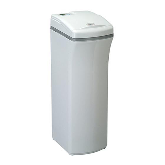
Models
EP 7130 & EP 7140
How to install, operate
and maintain your Demand
Controlled Water Softener
Do not return water softener to store
If you have any questions or concerns when
installing, operating or maintaining your water
softener, call our toll free number:
1-800-693-1138
Monday- Friday, 7 AM - 6 PM CST
(in Canada please call
www.ecopurewaterproducts.com
or visit
When you call, please be prepared to provide
the model and serial number of your product,
found on the rating decal, typically located on
the rim below the salt lid hinges.
Systems tested and certified by NSF International
against NSF/ANSI Standard 44
for hardness reduction and efficiency,
and certified to NSF/ANSI Standard 372.
1-866-725-9662
)
Manufactured and warranted by
Ecodyne Water Systems
1890 Woodlane Drive
Woodbury, MN 55125
7339913 (Rev. A 7/22/13)
Advertisement
Table of Contents
Troubleshooting

Related Manuals for Eco Pure EP 7130


Summary of Contents for Eco Pure EP 7130
- Page 1 Models EP 7130 & EP 7140 How to install, operate and maintain your Demand Controlled Water Softener Do not return water softener to store If you have any questions or concerns when installing, operating or maintaining your water softener, call our toll free number:...
-
Page 2: Table Of Contents
Exploded View & Parts List ..............22-27 WATER SOFTENER WARRANTY Warrantor: Ecodyne Water Systems, 1890 Woodlane Drive, Woodbury, MN 55125 Warrantor guarantees, to the original owner, that: One Year Full Warranty: ●... -
Page 3: Specifications & Performance Claims
Operational efficiency is the actual efficiency after the system has been installed. It is typically less than the rated efficiency, due to individual application factors including water hardness, water usage, and other contaminants that reduce a softener's capacity. Model EP 7130 Model EP 7140 Model Code... -
Page 4: Dimensions
Dimensions 21-1/4” Dimension Dimension MODEL 14-1/2” EP 7130 37-7/8” 3-3/8” EP 7140 38-1/8” 3-3/4” IN – OUT 44-3/4” FIG. 1 Safety Guides = The water softener requires a minimum water flow of 3 gallons per minute at the inlet. Maximum allowable inlet water pressure is 125 psi. -
Page 5: Inspect Shipment
Also inspect and note any damage to the them. shipping carton. Packing List Ground Clamp Installation Bypass Valve Bypass Valve Drain Hose Adaptors (Model EP 7130) (Model EP 7140) Water Hardness Test Strip O-rings (Model Clips Hose Clamps Adaptor Elbow Grommet EP 7140 only) FIG. -
Page 6: Installation Requirements
Installation Requirements LOCATION REQUIREMENTS PLUMBING CODES Consider all of the following when selecting an installa- All plumbing must be completed in accordance with tion location for the water softener. national, state and local plumbing codes. = Do not locate the water softener where freezing In the state of Massachusetts: The Commonwealth temperatures occur. -
Page 7: Installation Requirements
Installation Requirements VALVE DRAIN REQUIREMENTS 1/4” NPT Thread Barbs for 3/8” Using the flexible drain hose (included), measure and I.D. Tubing cut to the length needed. Flexible drain hose is not Hose Clamp allowed in all localities (check your plumbing codes). If local codes do not allow use of a flexible drain hose, a Drain Hose rigid valve drain run must be used. -
Page 8: Installation Instructions
Installation Instructions TYPICAL INSTALLATION Ground To Outside Conditioned Clamp Faucets Water Pipe Hard Water Ground Clips 1” NPT Sweat Clamp Water Softener Adaptor (not Valve Plug-in included) Transformer NOTE: Water Softener 1” NPT shown with Top Threaded Cover removed Adaptor Outlet O-ring Inlet... - Page 9 Installation Instructions TURN OFF WATER SUPPLY Brinewell Nozzle Cover Venturi Brine Tank 1. Close the main water supply valve, located near the Assembly Overflow well pump or water meter. Elbow 2. Shut off the electric or fuel supply to the water Nut - heater.
-
Page 10: Install Salt Storage Tank Overflow Hose
Installation Instructions COMPLETE INLET AND OUTLET PLUMBING INSTALL SALT STORAGE TANK OVERFLOW HOSE Measure, cut, and loosely assemble pipe and fittings from the main water pipe to the inlet and outlet ports of 1. Measure, cut to needed length and connect the 3/8" the water softener valve. - Page 11 Installation Instructions SANITIZE THE WATER SOFTENER / SANITIZE AFTER SERVICE If removing Care is taken at the factory to keep your unit clean and clips... sanitary. Materials used to make the unit will not infect or contaminate your water supply, and will not cause bacteria to form or grow.
-
Page 12: Programming The Water Softener
NOTE: If “- - - -” shows in the display, press the UP or DOWN button until the model code (“E7130” for Model EP 7130 or “E7140” for Model EP 7140) shows in the display. Then, press the SELECT / MENU button to set, and FIG. - Page 13 Programming the Water Softener SET RECHARGE (REGENERATION) TIME SET SALT LEVEL 1. Press the SELECT / MENU button once again to The water softener has a low salt indicator light to display a flashing “2:00AM” and the words “SET remind you to refill the storage tank with salt. RECHARGE TIME”.
-
Page 14: Customizing Features / Options
Customizing Features / Options RECHARGE NOW POWER OUTAGE MEMORY At times of greater than normal water use, such as If electrical power to the water softener is lost, “mem- when you have guests, you could run out of condi- ory'' built into the timer circuitry will keep all settings tioned water before the next scheduled recharge. -
Page 15: Customizing Features / Options
Customizing Features / Options SALT EFFICIENCY CALIFORNIA EFFICIENCY REQUIREMENT When this feature is ON, the water softener will oper- ate at salt efficiencies of 4000 grains of hardness per Your EcoPure Water Softener has a “High pound of salt or higher (May recharge more often Efficiency”... -
Page 16: Routine Maintenance
Routine Maintenance ADDING SALT CLEANING THE NOZZLE & VENTURI Slide open the salt lid and check the salt storage level A clean nozzle & venturi (See Figure 27) is a necessity frequently. If the water softener uses all the salt before for the water softener to work properly. - Page 17 Routine Maintenance PROTECT THE WATER SOFTENER FROM FREEZING If the softener is installed where it could freeze (sum- mer cabin, lake home, etc.), you must drain all water from it to stop possible freeze damage. To drain the softener: 1. Close the shut-off valve on the house main water pipe, near the water meter or pressure tank.
-
Page 18: Troubleshooting
Troubleshooting Guide PROBLEM CAUSE CORRECTION No soft water 1. No salt in the storage tank. Refill with salt and then use RECHARGE NOW feature. No soft water & dis- 1. Transformer unplugged at wall outlet, or Check for loss of power and correct. Reset electronic play is blank power cable disconnected from back of controls and then use RECHARGE NOW feature. -
Page 19: Troubleshooting
Open a nearby soft water faucet. a. Press the UP button to display the number of Model EP 7130: 000 to 199 (continual) = days this electronic control has had electrical Repeats for each gallon of water power applied. - Page 20 6. Press and hold the SELECT / MENU button until 1. Press the RECHARGE button and hold in for 3 the model code (“E7130” for Model EP 7130 or seconds. RECHARGE begins to flash as the sof- “E7140” for Model EP 7140) shows in the display.
- Page 21 Notes...
-
Page 22: Exploded View & Parts List
Softener Exploded View (Models EP 7130 & EP 7140) 70 or 121 Valve Assembly See Pages 24 - 27 for parts 72 or 123... - Page 23 Softener Parts List (Models EP 7130 & EP 7140, as listed below) Part No. Description Part No. Description Tank Neck Clamp Kit 7275907 Transformer – 7331177 (includes 2 ea. of Key Nos. 1 & 2) 7295046 Rim (order decal below) á...
- Page 24 Valve Exploded View Wear Strip Seal Cross-section View...
- Page 25 Valve Parts List (Model EP 7130) Part No. Description Part No. Description 7338111 Screw, #6-19 x 1-3/8” (2 req.) 7337571 O-Ring, 15/16” x 1-3/16”, pack of 4 Turbine & Support Assembly, 7281291 Motor – 7113040 including 2 O-Rings (See Key No.
- Page 26 Valve Exploded View (Model EP 7140) wear-strip seal cross-section view...
- Page 27 Adaptor Kit, 1” to 1-1/4” Not illustrated. To order repair parts call toll free 1-800-693-1138, Monday - Friday, 7 AM - 6 PM CST. Manufactured and warranted by Ecodyne Water Systems 1890 Woodlane Drive Woodbury, MN 55125 Questions? Call Toll Free 1-800-693-1138 Monday- Friday, 7 AM - 6 PM CST or visit www.ecopurewaterproducts.com...
Need help?
Do you have a question about the EP 7130 and is the answer not in the manual?
Questions and answers