Advertisement
Advertisement

Related Manuals for W2IHY EQplus

Summary of Contents for W2IHY EQplus
- Page 1 plus AUDIO PROCESSOR OPERATING MANUAL...
- Page 2 AUDIO PROCESSOR OPERATING MANUAL September 2004 W2IHY TECHNOLOGIES Julius D. Jones 19 Vanessa Lane Staatsburg, N.Y. (12580) (845) 889-4253 E-mail: Julius@W2IHY.COM Home Page: http:// www.w2ihy.com c 2004 W2IHY, ALL RIGHTS RESERVED...
-
Page 3: Table Of Contents
TABLE OF CONTENTS Introduction ......4 Front Panel Controls ..5 - 9 Rear Panel Controls ....10 - 11 Schematic (Front Panel) ..12 - 13 Schematic (Rear Panel) ..14 Rear Panel Controls ...15 Getting Started Tutorial ..16-19 Internal Wiring ....20 Audio Out Cable wiring .. -
Page 4: Introduction
Buying the EQplus gives you the availability to Amateur Service unrivaled in the hobby. We feel so confident that you will be delighted with the EQplus that we offer a 30 day money back, no questions asked guarantee. The EQplus represents the new reference point for easy to use amateur radio audio equipment. -
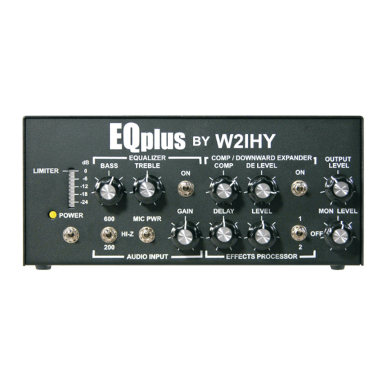
Page 5: Front Panel Controls
In and Aux Input connectors. The Mic power switch must be on if you have any of the following microphones connected directly into the EQplus: - ICOM HM12, HM36, SM6 etc.. - Heil microphones made specifically for ICOM radio’s such as... - Page 6 LED Bar Graph(6) . (6) LED Bar Graph The 10 segment LED Bar Graph indicates peak to peak EQplus internal audio levels. The position of the Equalizer (7) and Compressor / Downward Expander (10) switches control what internal function is being indicated.
- Page 7 0 dB of boost. Each case marking represents 4dB. (10) Compressor / Downward Expander On/Off Switch (S2) When the switch is in the off position the compressor and downward expander have no effect on the EQplus’s audio. (11) Compressor / Downward Expander COMPRESSOR (COMP) POTENTIOMETER (R22) This potentiometer works only if the Compressor / Downward Expander switch (10) is on.
- Page 8 Audio Input Gain Potentiometer or the Equalizer Potentiometers, will result in a small increase in output from the compressor’s circuitry. The good news is that the EQplus can produce high levels of compression while maintaining fidelity and very low distortion levels. The RF compressors in many radio’s have difficulty attaining high levels of compression with low levels of distortions.
- Page 9 The mixed waveform is next sent to the output of the EQplus. When the pot is turned clockwise, at the halfway point, there is a detent. This represents a starting point for adjusting the Effects Processor Delay..
-
Page 10: Rear Panel Controls
REAR PANEL CONTROLS (18) MIC SELECT This three position switch selects the YAESU, KENWOOD or ICOM microphone plugged into the 8 pin Mic Input (19). (Other microphones supported with mic adapters) (19) MIC INPUT This Input uses an 8 Pin microphone male connector. The impedance of this input is set by the Audio Input 3 position toggle switch (4). -
Page 11: Rear Panel Controls
Mic Select switch (18) and may be used for another audio input source such as a W2IHY 8 Band EQ. The impedance of this input is set by the Audio Input 3 position toggle switch (4). - Page 12 REAR PANEL CONTROLS (23) AUDIO OUTPUTS 1,2 and 3 The audio output and PTT outputs of the EQplus uses these 5 pin DIN’s. When the Audio Output Rotary switch (22) is in the “1” position, audio is active at Audio Output 1. When the Audio Output Rotary switch (22) is in the “2”...
-
Page 13: Getting Started Tutorial
If you are not using a mic but an external audio source like a W2IHY EQ, connect your audio source into the Aux Input. (If you are using a W2IHY EQ, then connect a cable between the Mic Out of the EQ and the Aux Input of the EQplus.) - Page 14 2 or 3 Green Bar Graph LED’s light up. This may require adjusting both the Mic Gain control on the 8 Band EQ and the Audio Gain control on the EQplus. Using The EQplus headphone (PHONES) Monitor Connect a set of stereo headsets into the 1/4 inch “...
- Page 15 Limiting of audio signal levels occur when the Compressor is on and the internal audio signals exceed -9db (first yellow LED on). The EQplus creates no perceptible distortion to audio that is heavily compressed. - The...
- Page 16 Program 2 ( Effects Processor toggle switch (13) selecting 2) simulates audio reflecting from a surface once. With your radio connected to the EQplus, adjust the Output Level control (16) to a level that properly drives your radio. Turning the Output Level control clockwise increases the output of the EQplus.
-
Page 17: Internal Wiring
INTERNAL WIRING PIN 7 PIN 1 MIC IN -20-... -
Page 18: Audio Out Cable Wiring
AUDIO OUT CABLE WIRING 5 PIN DIN AUDIO OUTPUT CONNECTION + Audio Balanced AUDIO OUT 1/2/3 Output - Audio 5 Pin Male DIN Hi-Z Output Din connectors shown on side to be soldered Low Impedance Balanced Output to Low Impedance Radio + Audio Balanced AUDIO OUT 1/2/3... - Page 19 AUDIO OUT CABLE WIRING + Mic 8 Pin Mic Connector Pin 8 Japan Radio - Mic 8 Pin Mic Connector Pin 7 JST-135 JST-245 Yaesu 8 Pin Mic Connector Pin 6 FT990/ft992 Shield of Cable FT1000MP/M-V 8 Pin Mic Connector Pin 5 + Mic Alinco DX77 8 Pin Mic Connector Pin 1...
- Page 20 AUDIO OUT & POWER CABLE WIRING + Audio - Audio DRAKE T4XB COLLINS 32S 1, 32S3 HI-Z COLLINS KWM2A Shield of Cable + Audio 2 Pin Mic Connector Pin 1 - Audio HI-Z COLLINS 32V2, 32V3 Hallicrafters 2 Pin Mic Connector Pin 2 E.F.
- Page 21 AUDIO OUT CABLE WIRING + Audio - Audio LOW Z TRS BALANCED OUTPUT LOW-Z Shield of Cable + Audio - Audio HI Z TRS BALANCED OUTPUT HI-Z Shield of Cable + Audio - Audio LOW Z XLR BALANCED OUTPUT LOW-Z Shield of Cable - Audio HI-Z...
Need help?
Do you have a question about the EQplus and is the answer not in the manual?
Questions and answers