Table of Contents
Advertisement
Quick Links
Advertisement
Table of Contents

Related Manuals for Alcons ALC2

Summary of Contents for Alcons ALC2
- Page 2 Certificates _____________________________________________________...
-
Page 3: Table Of Contents
3. Precautions_____________________________________________________________________________________________ 8 4. Installation _____________________________________________________________________________________________ 9 5. Overview ______________________________________________________________________________________________ 12 6. Connections ___________________________________________________________________________________________ 15 7. Operation _____________________________________________________________________________________________ 22 8. Safety ________________________________________________________________________________________________ 24 9. Service and support_____________________________________________________________________________________ 26 10. Specifications_________________________________________________________________________________________ 28 11. Block diagram ________________________________________________________________________________________ 29 ALC2 User’s Manual. Rev. 01... -
Page 4: Introduction
1. Introduction___________________________________________________ Dear customer, Congratulations on your purchase of an Alcons Audio ALC2 professional power amplifier, and thank you for your confidence in Alcons products. We are very honoured to welcome you to the growing family of Alcons ambassadors! For your safety, please read the Important safety instructions and the Precautions section before installing and operating the amplifier. - Page 5 (passive system). High efficient Class-G power stages The ALC2 is equipped with two class-G power amplifiers for increased thermal efficiency, while also saving weight on the heat sinks and the power supply. SIS Signal Integrity Sensing SIS is a unique feature installed in all Alcons amplifiers that senses the signals arriving at the loudspeaker terminals, and so compensating for errors introduced by cable resistance and self-induction.
- Page 6 RF and ultrasonic protection A RF sensing circuit is continuously monitoring the inputs of the ALC2 to detect ultrasonic energy. When RF energy is detected, the inputs of the ALC2 are muted to prevent damaging your loudspeakers or the amplifier.
-
Page 7: Important Safety Instructions
The exclamation point within a triangle is intended to alert the user to the presence of important operating instructions in the literature accompanying the product. ALC2 User’s Manual. Rev. 01... -
Page 8: Precautions
- Refer servicing to qualified service personnel. Servicing is required when the amplifier has been damaged in any way, liquid has been spilled on or into the amplifier, does not operate normally or has been dropped. - Do not series or parallel connect an amplifier output with any other amplifier output. Connecting outputs together can cause damage to the amplifiers. ALC2 User’s Manual. Rev. 01... -
Page 9: Installation
Unpacking Carefully open the shipping carton and inspect the amplifier. Every Alcons amplifier is thoroughly tested and inspected before leaving the factory and should arrive in perfect condition. If you find any damage, notify the shipping company immediately. Only you, the consignee, may initiate a claim for shipping damage. - Page 10 Cooling and ventilation The ALC2 amplifier uses forced air cooling in order to maintain a low operating temperature. In the ALC2 the cooling air enters at the front and the hot air leaves the amplifier at the left side. The reason for this is that the air outside the rack is usually cooler than inside, and therefore the amplifiers can run at higher continuous power levels without thermal problems.
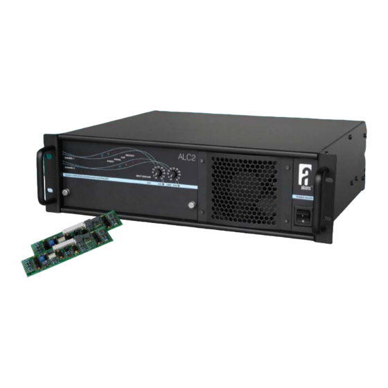
- Page 11 Place the SDP modules with the component-side up in the SDP connectors. The upper connector is for channel 1 or mono bridge mode operation, the lower one is for channel 2. The modules lock into position and do not need to be secured. The ALC2 automatically routes the signals through the modules once they have been inserted.
-
Page 12: Overview
When these LEDs are constantly illuminated, the amplifier is in ‘protect’ mode and the signal to the amplifier is muted. This indicates either: High temperatures in the amplifier’s output section or power supply, RF on the input, DC on the output. These LEDs also illuminate during power-up. ALC2 User’s Manual. Rev. 01... - Page 13 13 Air inlet grill Cooling air inlet grill. Make sure this inlet remains clear to allow unrestricted air intake. 14 AC power switch This control switches the mains supply for the amplifier on or off. Rear panel ALC2 User’s Manual. Rev. 01...
- Page 14 This three pole male XLR connector is internally hardwired to the channel 1 input connector. You can use this connector to ‘daisy chain’ the channel one input signal to the next amplifier. 10 Data port Through this 15 pin high density D-connector, a remote control processor or cinema booth monitor can be connected ALC2 User’s Manual. Rev. 01...
-
Page 15: Connections
Loudspeakers are connected using Speakon® connectors. For each channel two Speakon® connectors are available which are connected in parallel. Due to the SIS (Signal Integrity Sensing) feature on the ALC2, there are four connections per channel instead of two. The two extra wires are used for voltage sensing at the loudspeaker terminals. - Page 16 The Speakon® connector is wired as follows: Speakon® male plug viewed from the wiring side. 1+ = Output + 1- = Output – 2+ = Sense + 2- = Sense – Normal loudspeaker connection. Connection without SIS. ALC2 User’s Manual. Rev. 01...
- Page 17 In the next table a few percentages are converted to dBs: % loss dB loss 0.1 dB 0.2 dB 0.4 dB 10 % 0.9 dB 15 % 1.4 dB 20 % 1.9 dB 25 % 2.5 dB 30 % 3.1 dB 35 % 3.7 dB ALC2 User’s Manual. Rev. 01...
- Page 18 SIS to the channel 1 and channel 2 outputs, and your signals to the channel 1 and channel 2 inputs. In this mode each channel can have its own SDP module and uses its own gain control. ALC2 User’s Manual. Rev. 01...
- Page 19 SIS to the channel 1 and channel 2 outputs, and your signal source to the channel 1 input. In this mode each channel can have its own SDP module and uses its own gain control. ALC2 User’s Manual. Rev. 01...
- Page 20 2 outputs as shown above. Connect your signal source to the channel 1 input. In this mode only the channel 1 SDP module can be used. The channel 1 gain control sets the gain for the entire amplifier. Remember, that in bridge mode the amplifier cannot cope with loads lower than 4 Ω. ALC2 User’s Manual. Rev. 01...
- Page 21 Data port The Data port located on the rear panel of the ALC2, is the connection for remote controlling the amplifier. Through the 15 pin high density D-connector, signals indicating the status of the ALC2 are available for the remote control unit. The input signals to the amplifier can also be supplied through this connector.
-
Page 22: Operation
DC. Usually this indicates a defect in the amplifier and the need for servicing. 3. High temperature. When it is flashing, the output section of the related channel is between 85 and 90 degrees centigrade (185 - 194° F),and the ALC2 has shut down its class-G stage. - Page 23 Gain is controlled by the channel 1 gain potentiometer. In this mode only the channel 1 SDP module can be used. You can use standard SDP protection modules in bridge mode. The ALC2 automatically recalculates the limit thresholds to compensate for the extra gain of the amplifier.
-
Page 24: Safety
Temperature protection The ALC2 is cooled by a large 120 mm (4.7 in.) variable speed fan located behind the grill on the front panel. Fan speed increases only as required by measured temperatures, keeping fan noise to a minimum. Under extreme thermal load the fan will force a very large volume of air through the heat sinks. If either one of the heat sinks or the toroidal power transformer surpasses the maximum allowed temperature, the ALC2 temperature protection circuits become active. - Page 25 AC inrush limiter The AC inrush limiter is active when the ALC2 is switched on. The AC mains inrush current is limited to a safe value. However, take care not to switch-on too many amplifiers at the same time, or you may risk that the main fuses of your AC distribution will blow.
-
Page 26: Service And Support
Summary Alcons Audio BV warrants the original purchaser and any subsequent owner of each new Alcons product, for a period of three years from the date of the original purchase by the original purchaser that the new Alcons product is free of defects in materials and workmanship. Alcons Audio BV warrants the new Alcons product regardless of the reason for failure, except as excluded in this warranty. - Page 27 9. Service and support ____________________________________________ Contact information Mailing address: Alcons Audio BV De Corantijn 69 1689 AN ZWAAG The Netherlands Telephone / Facsimile: Telephone: +31 (0)229 283090 Fax.: +31 (0)229 283099 World Wide Web: http://www.alconsaudio.com E-mail: info@alconsaudio.com ALC2 User’s Manual. Rev. 01...
-
Page 28: Specifications
____________________________________________________________________________________ 21.0 kg / 46 lb Housing _______________________________ 19 inch rack mount, 3 HU, 387 mm / 15.2 inch deep behind the mounting surface Dimensions _________________________________________ 132x482x430 mm / 5.2x19x16.9 inch (hxwxd) including rack handles ALC2 User’s Manual. Rev. 01... -
Page 29: Block Diagram
11. Block diagram ________________________________________________ ALC2 User’s Manual. Rev. 01...
Need help?
Do you have a question about the ALC2 and is the answer not in the manual?
Questions and answers