Table of Contents
Advertisement
Advertisement
Table of Contents

Summary of Contents for ETEK AD 1823
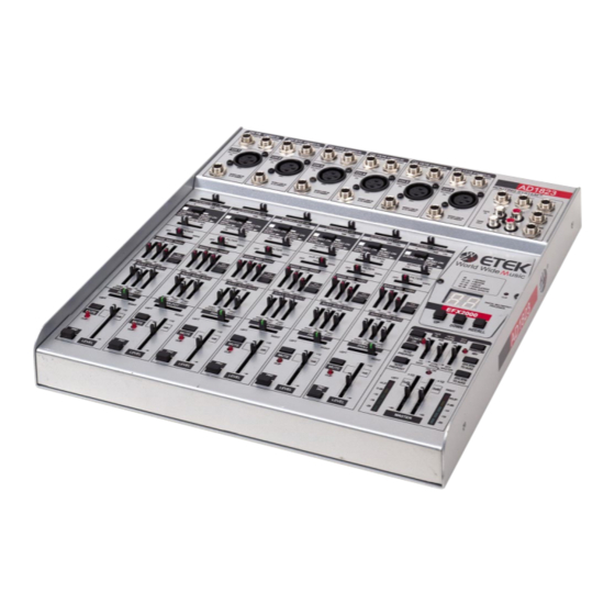
- Page 1 ENGLISH Model AD 1823 18-CHANNEL ANALOG MIXER OWNER’S MANUAL...
-
Page 2: Safety Precautions And Instructions
SAFETY PRECAUTIONS AND INSTRUCTIONS CAUTION RISK OF ELECTRIC SHOCK DO NOT OPEN CAUTION TO REDUCE THE RISK OF ELECTRIC SHOCK NOT REMOVE COVER NO USER SERVICEABLE PARTS NSIDE REFER SERVICING TO QUALIFIED PERSONNEL EXPLANATION OF GRAPHIC SYMBOLS: The arrowheaded lightning flash symbol, inside an equilateral triangle, is intended to alert the user to the presence of “dangerous voltages”... -
Page 3: Important Safety And Installation Instructions
IMPORTANT SAFETY AND INSTALLATION INSTRUCTIONS WARNING – When using electrical products, basic precautions as follow must be observed: 1. Read all the safety, installation and operating instructions before using the product and refer to the instructions on pages 1, 2 and 3 to ensure a correct and safe installation. 2. - Page 4 SPECIAL INSTRUCTIONS FOR USE IN GREAT BRITAIN IMPORTANT The wires in the mains lead are coloured according to the following code: Green – and – Yellow > Earth Blue > Neutral Brown > Live The wires in the mains lead of this instrument may not correspond with the coloured markings, you should therefore refer to this diagram to identify the terminals in your plug: Connect the GREEN and YELLOW earth wire to the...
-
Page 5: Special Notes
SPECIAL NOTES In addition to the Safety Precautions and Instructions outlined on pages 1, 2 and 3, the following notes should be read and adhered to. POWER SUPPLY When connecting the mixer to other equipment, always carry out the operations with the power to all the equipment turned ‘Off’;... -
Page 6: Table Of Contents
4.7 MUTE ................................12 STEREO INPUT CHANNELS ..........................13 5.1 INPUT LEVEL...............................13 INSERTS ................................14 6.1 WHAT ARE INSERT POINTS ........................14 6.2 AD 1823 INSERTS............................14 MASTER SECTION ..............................15 7.1 INPUTS/OUTPUTS ............................15 7.1.1 AC POWER IN ..............................15 7.1.2 LEFT OUTPUT and RIGHT OUTPUT ....................... 15 7.1.3... -
Page 7: Using The Manual
USING THE MANUAL INTRODUCTION With your purchase of an ETEK MIXER you have entered into the world of ETEK professional sound equipment. This mixer is built to top quality standards and will ensure trouble-free performance for your recording sessions or live concerts. This manual will cover all the sections of the mixer and all the controls in each of these sections, explaining their use and setup. -
Page 8: Control Panel Reference Chart
CONTROL PANEL REFERENCE CHART AD 1823 CONTROL PANEL REFERENCE CHART LEFT OUTPUT RIGHT OUTPUT AC POWER IN REAR PANEL PB 2 PB 1 PB 3 S 10 PB 6 S 11 S 14 PB 9 S 12 S 15 S 16... -
Page 9: Layout Of The Mixer
Master section via Pan-Pots (S 13). AUX SENDS Three Aux Send busses are available in the AD 1823. Each has its own send level control in each channel. AUX 1 is stereo and AUX 2 /AUX 3 can be made to be Pre/Post Fader functional, selected by a push button switch (PB 7, PB 8). -
Page 10: Power Supply Unit
This problem has been eliminated by the AD 1823 with the use of a specially designed 35 VA Power Supply Unit. The Heavy-Duty unit is connected externally to reduce possibility of noise and hum pickup and ensure the best possible sound quality. -
Page 11: Routing System
ROUTING SYSTEM All the models in the AD range of ETEK mixers have a Patents Pending feature called the ROUTING SYSTEM. This system is the best way to have Mono and Stereo channels simultaneously, thus multiplying the input possibilities, within the smallest dimensions. -
Page 12: Mono Input Channels
4. MONO INPUT CHANNELS Each MONO channel has a balanced line XLR MIC input and an unbalanced LINE 1/4” jack input. The wide range gain circuitry used, from –50 dB to +10 dB, means that both line and mic signals can be used without the need for switching. The GAIN setting for the Mono channels is achieved by means of the MONO IN GAIN slider (S 5). -
Page 13: Pan Control
PAN CONTROL The PAN-POT (S 13) sets the position of the channel output within the stereo spectrum, from left to right with the detent indicating the centre position. CHANNEL FADING The final feed from each channel to the Main Bus passes through the LEVEL slider (S 3), designed to give a smooth mix up/down of the signal from each channel. -
Page 14: Stereo Input Channels
STEREO INPUT CHANNELS Each STEREO channel has two line inputs into 1/4” jacks for the Right and Left input signals. When only the Right socket is used, this operates as the Mono Input, and this Mono signal is fed to both Right and Left channels. A further input possibility is available when using the LEFT input only with a Stereo jack plug. -
Page 15: Inserts
AD 1823 INSERTS Four inserts are provided on the channels of the AD 1823. These employ the same jack as the Mono Line In and should be connected using the Stereo jack wiring for the Pre-Gain Inserts shown shown in Fig. 8.1. -
Page 16: Master Section
MASTER SECTION INPUTS / OUTPUTS Several Input and Output facilities are provided in the Master Section of the AD 1823. Apart from the MAIN MIX OUTS (LEFT OUT and RIGHT OUT) on the back panel, 3 AUX OUT; HEADPHONE; STEREO RETURN and TAPE IN/TAPE OUT sockets are also available in the section in the top right hand corner of the control panel. -
Page 17: Push Button Controls
PUSH BUTTON CONTROLS Several push buttons are to be found in the MASTER section. These are POWER ON (PB 1), PHANTOM 48V (PB 6), AUX 2 PRE/POST (PB 7), AUX 3 PRE/POST (PB 8), EFX RTN TO AUX 2 (PB 9) and EFX RTN TO AUX 3 (PB 10). -
Page 18: Input/Output Plug Connections
INPUT/OUTPUT PLUG CONNECTIONS In order to be able to make all the necessary connections to your mixer, various different types of plugs are needed. Check out the types in Fig. 8.1 below in order to prepare or buy the right leads before setting up the mixer. -
Page 19: Jack Plug Connections For Special Applications
Sleeve = Sleeve = Ground/Screen Ground/Screen Ring = Send Signal and Tip = Return Signal Tip = Signal (Connected together) To Tape or FX Input To Channel Insert Fig 8.2.1 ‘Tapped' Connection Direct Output Lead Enables the Insert to be used as a Direct Output while maintaining the channel signal flow) Sleeve Ring... -
Page 20: Setting Up
SETTING UP SELECTING INPUTS Mono Channels are used with both Mic or Line Inputs. It goes without saying that if you are using the Mic Input, make sure no signal is applied to the Line input (and vice-versa). Mic Inputs are always a lot more sensitive than the Line Inputs. Remember not to plug mics into the XLR sockets with Phantom Power switched on. -
Page 21: Mixer's Normal Settings
If an Insert is used to connect an external unit such as a compressor, gate, EQ etc., use the external processor's Bypass or Effect switch to A/B monitor the signals with and without the effect, which should be level matched. (If no bypass switch is available, you will have to connect and disconnect the unit until you achieve unity gain.) Set the PRO PFL push button to the 'UP' position and move to the next channel to be set up. -
Page 22: Track Assignment
Look out for inaccurate/uncalibrated sampler input meters. Find out how hard you can safely push the sampler's input, refer this to 0 dB on an AD 1823 output (PFL), then take note of the same input gain slider setting. Now you can use the LED bargraph meters to confirm level when sampling, much better than using the Sampler's input level display. -
Page 23: 10. About Mixing
10.1 EQUALIZATION The parameters of the Channel Equalizers of the AD 1823 are described in section 4.3. Most people know how an equalizer works. How to use it to its best advantage is desribed below. An equalizer was once considered as an instrument for removing or attenuating frequencies, improving bad microphone sounds or compensating for frequencies that are accentuated or are missing in an environment where a recording is made. -
Page 24: Un) Balanced Line Connections
-to -noise ratio will be. The performance of particularly noisy Efx units or synthesizers can be greatly improved by the use of an external Noise Reduction Processor such as the ETEK OPTIMA Digital Rack Module in the Efx loop. - Page 25 Microphone Lines Most mics carry signals of a magnitude of millivolts not volts. The protection of such a low level signal is much more complicated. In Section 11.2 the problem of signal-to-noise ratio was covered. Here the same problem exists, because whereas with a signal of 50 volts the effect of any mains interference is minimal, with a signal that can be a thousand times smaller the ratio is obviously smaller.
-
Page 26: 11. Expansion
11. EXPANSION 11.1 EFX 2000 20-BIT DIGITAL MULTI- EFFECTS MODULE The AD 1823 can be expanded to include the EFX 2000 20-Bit Digital Multi-Effects Module by substituting the removable panel above the Master section of the control panel of the mixer. -
Page 27: Pa 400 200W + 200W Power Amplifier
11.2 PA 400 200 W + 200 W POWER AMPLIFIER This powerful amplifier has been designed to be mounted on the lower panel of the mixer. The amp is contained in a metal box of the same style as that of the mixer. It is provided with a connector on the top panel, for the connection to the mixer, and 4 fixing screws... -
Page 28: 12. Glossary Of Terms
Degree of amplification. Headroom Signal range between nominal level and clipping. High Pass Filter Cuts off low frequencies. The cut-off point can be variable as is the case in the H.P. Filter of the ETEK AD 1823. Howlround see Feedback. - Page 29 Lo Cut Filter see High Pass Filter. Mixdown Process by which a multi-track recording is combined into e.g. one or two channels. Mute (Mute Button) To silence (Signal muting button). Normal Means to connect an output to an input via a breakable link, like in an insert circuit. see Balance.
- Page 30 Corso Persiani, 44 - 62019 Recanati (MC) Italy www.etekengineering.com Info@etekengineering.com...
Need help?
Do you have a question about the AD 1823 and is the answer not in the manual?
Questions and answers