Table of Contents
Advertisement
Contents
Main features .......................................................................................... 3
Specifications ......................................................................................... 4
SD3 panel layout ..................................................................................... 4
General .................................................................................................. 5
Mounting instructions .............................................................................. 5
SD3 internal board layout ....................................................................... 5
Control panel (SELV) connections ........................................................6
Telephone (TNV) connections .............................................................. 7
GSM module installation .......................................................................... 8
GSM module operation .................................................................10
Getting started ..................................................................................... 11
Using the programming menu .............................................................. 12
Accessing the programming menu ....................................................12
Exiting from the programming menu ..................................................12
Programming menu options .............................................................. 12
Basic setup ....................................................................................... 12
Programming menu options list ............................................................. 13
Contact Details .................................................................................. 14
Messages ........................................................................................ 15
Voice messages ............................................................................15
Text messages ..............................................................................16
System Options ................................................................................. 17
Trigger Polarity ..............................................................................17
Remote Options ............................................................................17
SMS Options .................................................................................18
Display Options .............................................................................18
Alarm Levels ..................................................................................19
Record Options .............................................................................19
Report Options ..............................................................................19
Line Priority ...................................................................................19
Access Codes ................................................................................... 20
Acknowledgement and Abort Options ..............................................21
2
Abort Options ................................................................................21
Clear by Options ...........................................................................21
Outputs ............................................................................................. 22
Call Routing Options ......................................................................... 23
5
Set Date and Time ............................................................................ 23
View Log ........................................................................................... 24
Test Options ...................................................................................... 25
Test Messages ..............................................................................25
Test Outputs .................................................................................26
Test Triggers ..................................................................................26
Test Line ........................................................................................27
Test Supply ...................................................................................27
11
GSM Phone Utilities ......................................................................27
Software Version ...........................................................................28
How to acknowledge a voice message ................................................. 29
Aborting an alarm call ............................................................................ 29
Recording and playing a memo locally .................................................. 29
Using the remote access feature ........................................................... 30
Remote access by dialling in ............................................................. 30
Remote access via an alarm call ........................................................ 30
The remote access menu .................................................................. 31
Toggle outputs .................................................................................. 31
Listen-in & talkback mode ................................................................. 31
Testing triggers remotely .................................................................... 32
Entering contact numbers remotely ...................................................32
Remotely recording and playing messages ........................................32
Alarm voice and restore messages ................................................32
Memo messages ...........................................................................32
Text Editing Keys .................................................................................. 33
Declaration of Conformance .................................................................. 34
29
1
Advertisement
Table of Contents

Summary of Contents for Cooper Menvier SD3
-
Page 1: Table Of Contents
Set Date and Time ................23 General ....................5 View Log ................... 24 Mounting instructions ................5 Test Options ..................25 SD3 internal board layout ............... 5 Test Messages ................25 Control panel (SELV) connections ............6 Test Outputs .................26 Telephone (TNV) connections .............. 7 Test Triggers ..................26... -
Page 2: Introduction
The SD3 Speech Dialler provides a means of communicating information to fixed and mobile telephones. You can either connect the SD3 to an alarm control panel (taking advantage of its power supply and battery backup) or use the SD3 in a standalone role. -
Page 3: Main Features
Contacts Temperature sensor The SD3 allows you to store up to 10 contacts: you can assign each one a name, The SD3 displays the current ambient temperature. You can program temperature telephone number, message type, and acknowledgement type. high and low alarms, linking them to two corresponding output types. -
Page 4: Specifications
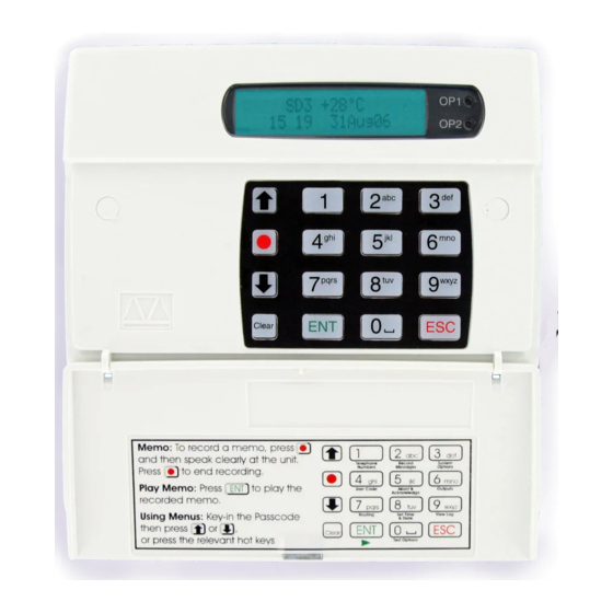
Specifications SD3 panel layout Supply voltage: 10.5 - 28VDC Current consumption (@12VDC): 50mA (Standby), 170mA (Active) Red indicator Trigger Inputs: Eight: positive/negative applied or shows the sta- positive/negative removed (5 - 24VDC) Two-line backlit tus of Output 1 LCD display SD3 +24°C... -
Page 5: Installation
Installation General SD3 internal board layout The SD3 is designed to connect to an intruder alarm control panel or similar. The SD3 requires a power input (from an alarm control panel or separate power Upper connector Microphone Sounder/loudspeaker supply) of between 10.5V and 28V, with a supply capability of 100mA or greater. -
Page 6: Control Panel (Selv) Connections
Connect these terminals to the relevant outputs on the alarm control panel. When ADE Optima 6 13V+ 13V- an alarm panel triggers an input, the SD3 initiates the calling sequence and plays ADE Optima XM 13V+ 13V- the relevant speech and/or text message. The diagrams below show the various C&K 800L... -
Page 7: Telephone (Tnv) Connections
Telephone (TNV) connections The easiest way to connect the SD3 to the telephone line is to use the telephone lead that is provided with the unit as shown below: However, if the lead is not long enough or a serial connection is required the SD3... -
Page 8: Gsm Module Installation
GSM module installation The GSM module is a plug-in board for the SD3 Speech Dialler that allows it to If necessary, remove the SD3 unit from the wall fixings and remove the two screws holding the front panel and backbox together. - Page 9 10 Re-connect all previously removed connections (including power). 11 Re-attach the SD3 panel onto the backbox and refit the two screws holding the case together.
-
Page 10: Gsm Module Operation
(See below.) down on the top up card. Note that the SD3 cannot support the text message response service calls using The table below provides spaces for you record the relevant information about the * and # keys. You must call the service provider manually and either register your GSM installation. -
Page 11: Commissioning
Getting started When beginning a new installation, it is advisable to prompt the SD3 unit to make a factory reset in order to ensure that any existing settings are removed. -
Page 12: Using The Programming Menu
In the majority of installations you can set up the SD3’s basic functions by using Note: Please note for correct operation it is necessary to exit the programming in only the following programming menu options: the manner described below. -
Page 13: Programming Menu Options List
1 Ring Answer Trigger Restore Clear by Options SMS Options Route A Restore To Anyone SMS Call Number Route B Restore To No One SMS Format … SMS Protocol Route H Restore To SD3 Tel. Number Auto Report Route Auto Rep. To... -
Page 14: Contact Details
Text Only programming you can clear the last digit by pressing the (Clear) key. The SD3 dials the SMS service centre and relays the relevant text message to the Contact’s telephone number. 6 Press to accept the telephone number. The display now shows the contact... -
Page 15: Messages
Record Alarm A When calling some mobile phone networks you may find that the network takes a SPEAK NOW...04s long time to connect to the mobile unit, causing the SD3 to drop the call and move 5 Press to stop recording. -
Page 16: Text Messages
(Short Message Service) messaging. The unit can store up to eight alarm mes- sages, each with up to 40-characters. Note: The optional GSM module is required to allow the SD3 to send text messages. When the unit sends a text message, it adds the “site message” with a time and... -
Page 17: System Options
Alarm Levels Internal alarm triggers: temperature and power supply. to dial into the SD3 unit, even when it shares the line with other ‘answering devic- es’ such as answerphones or fax machines. Be sure to set the ‘Rings to Answer’... -
Page 18: Sms Options
This option allows the editing of the default SMS service centre number used by • If enabled ( ), the SD3 will flash the display backlight on and off when a memo the SD3 to send text messages. message is waiting (default). Listening to the memo message stops the back- light flashing. -
Page 19: Alarm Levels
This option allows you to set the temperature at which the temperature high alarm If enabled ( ), the SD3 will automatically call any programmed numbers in the output will activate (see also Outputs). Working range of 0°C to 50°C (default ‘... -
Page 20: Access Codes
Access Codes The SD3 operation is protected by two main codes: • The user code A 4-digit code which is required, when using the unit locally, to gain access to the programming menus. The user code is also used for aborting calls. -
Page 21: Acknowledgement And Abort Options
Clear by Options Abort Options Once the SD3 has made its call and delivered its message it requires a sig- Occasionally, the SD3 may be triggered accidentally, causing it to send an unwant- nal, from the contacted person, to say that the message has been successfully ed call. -
Page 22: Outputs
Outputs The SD3 has four programmable outputs (OP1 to OP4) that can be accessed re- motely and used for a wide variety of functions (for example: switching on lighting or heating/ventilation systems). To program an output 1 From standby, enter the user code, then use the scroll keys (... -
Page 23: Call Routing Options
Call routing options allow you to determine which contacts should receive certain This option allows you to adjust the SD3’s date and time. The clock is in 24-hour (voice or text) messages. For instance, you may require alarm message A to be... -
Page 24: View Log
View Log Log event codes The SD3 has a time and date-stamped event log that records a range of detected occurrences, such as power failures, date changes, trigger inputs and the recipi- Display Description ents contacted. The log has capacity for 128 entries and retains all information A trigger on input A to H has been sensed. -
Page 25: Test Options
Test Options Test Messages The SD3 has seven test options: This menu allows you to test the voice messages. The unit will call the selected Test Messages contacts and play the selected voice message. Test Outputs To test messages... -
Page 26: Test Outputs
Test Outputs Test Triggers This test menu allows you to test the SD3’s outputs by switching them on and off This test menu allows you to view the response to trigger inputs . as required. To test triggers To test outputs... -
Page 27: Test Line
Test Line GSM Phone Utilities This test menu allows you to test the SD3’s fixed telephone line (not GSM mobile) These utilities allow you to check various aspects of GSM operation, when the status. optional GSM module is fitted. To test the line... -
Page 28: Software Version
Software Version This option displays the current SD3 internal software version. To view the software version 1 From standby, enter the user code, then use the scroll keys ( ) or display the menu: Test Options Test Options Press to select. The screen will show the first option:... -
Page 29: Operation
The SD3 requires a call acknowledgement in order to confirm that the recipient has The SD3 has an in-built memo facility to record a voice memo message at the accepted the call. All contacts must be informed, both in advance and within the keypad that can be up to sixteen seconds in duration. -
Page 30: Using The Remote Access Feature
This method requires you to call into the SD3 in order to select the remote access If an alarm has been triggered, when the SD3 makes its alarm calls, it is possible menu. You will need to enter the remote code (by default: 5678). -
Page 31: The Remote Access Menu
The remote access menu Toggle outputs The following commands can be selected from the remote access menu using the The remote access menu allows you to change (toggle) the on/off state of the SD3 keypad of your touch-tone phone: outputs 1 to 4. -
Page 32: Testing Triggers Remotely
Testing triggers remotely 2 Select the required options, as follows: You can test the SD3 unit’s response to any of the eight triggers remotely via a telephone link. • To record an alarm voice message: Press 4 followed by the voice message... -
Page 33: Text Editing Keys
Text Editing Keys Text is programmed in a similar way to mobile phones. Characters are selected by pressing the corresponding key the appropriate number of times (to select a character on the same key, wait for the cursor to automatically advance). The table below shows the keys to use and the characters that are assigned to them: Characters “... -
Page 34: Declaration Of Conformance
Declaration of Conformance © Cooper Security Ltd. 2006 This product complies with the 1995/5/EC R&TTE Directive. Part Number 11702491 Issue 1 For further details, please see: www.coopersecurity.co.uk Every effort has been made to ensure that the contents of this book are correct. However, neither the authors nor Cooper Security Limited accept any liability for loss or damage caused or alleged to be caused directly or indirectly by this book. - Page 35 SD3 Speech Dialler SD3 +24°C 12:01 06Jul06 Installation and Operation Guide pqrs wxyz Clear...
Need help?
Do you have a question about the SD3 and is the answer not in the manual?
Questions and answers