Table of Contents
Advertisement
Advertisement
Table of Contents

Subscribe to Our Youtube Channel
Related Manuals for Jensen JTM-105A


Summary of Contents for Jensen JTM-105A
- Page 1 User’s Guide True RMS Industrial Multimeter Model JTM-105A...
- Page 2 Introduction Congratulations on your purchase of the Jensen JTM-105A True RMS Autoranging Multimeter. This meter measures AC/DC Voltage, AC/DC Current, Resistance, Capacitance, Frequency (electrical & electronic), Diode Test, and Continuity plus Thermocouple Temperature. It features a waterproof, rugged design for heavy duty use. Proper use and care of this meter will provide many years of reliable service.
- Page 3 OVERVOLTAGE CATEGORY IV Equipment of OVERVOLTAGE CATEGORY IV is for use at the origin of the installation. Note – Examples include electricity meters and primary over-current protection equipment JTM-105a V3.0 10/07...
-
Page 4: Safety Instructions
NEVER operate the meter unless the back cover and the battery and fuse covers are in place and fastened securely. If the equipment is used in a manner not specified by the manufacturer, the protection provided by the equipment may be impaired. JTM-105a V3.0 10/07... -
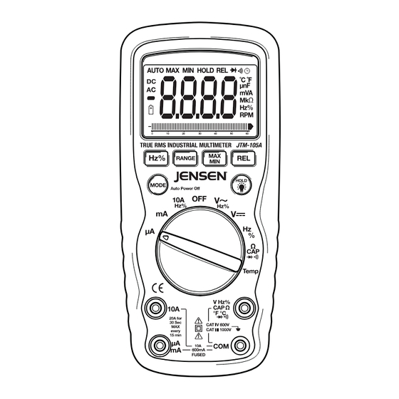
Page 5: Controls And Jacks
6. mA, µA and 10A input jacks 7. COM input jack 8. Positive input jack 9. HOLD and Backlight button 10. RELATIVE button 11. MAX/MIN button Note: Tilt stand and battery compartment are on rear of unit. JTM-105a V3.0 10/07... -
Page 6: Symbols And Annunciators
Amps kilo (10 ) (ohms) Farads (capacitance) mega (10 ) (ohms) Ω Ohms Hertz (frequency) Volts Percent (duty ratio) Relative Alternating current AUTO Autoranging Direct current HOLD Display hold ºF Degrees Fahrenheit ºC Degrees Centigrade Maximum Minimum JTM-105a V3.0 10/07... -
Page 7: Dc Voltage Measurements
Insert the red test lead banana plug into the positive V jack. 3. Touch the black test probe tip to the negative side of the circuit. Touch the red test probe tip to the positive side of the circuit. 4. Read the voltage in the display. JTM-105a V3.0 10/07... -
Page 8: Ac Voltage (Frequency, Duty Cycle) Measurements
4. Read the voltage in the display. 5. Press the HZ/% button to indicate “Hz”. 6. Read the frequency in the display. 7. Press the Hz/% button again to indicate “%”. 8. Read the % of duty cycle in the display. JTM-105a V3.0 10/07... -
Page 9: Dc Current Measurements
7. Touch the black test probe tip to the negative side of the circuit. Touch the red test probe tip to the positive side of the circuit. 8. Apply power to the circuit. 9. Read the current in the display. JTM-105a V3.0 10/07... -
Page 10: Ac Current (Frequency, Duty Cycle) Measurements
10. Press the Hz/% button to indicate “Hz”. 11. Read the frequency in the display. 12. Press the Hz/% button again to indicate “%”. 13. Read the % duty cycle in the display. 14. Press the Hz/% button to return to current measurement. JTM-105a V3.0 10/07... -
Page 11: Resistance Measurements
4. Touch the test probe tips to the circuit or wire you wish to check. 5. If the resistance is less than approximately 35Ω, the audible signal will sound. If the circuit is open, the display will indicate “OL”. JTM-105a V3.0 10/07... -
Page 12: Diode Test
(about 30 seconds). 5. Read the temperature in the display. Note: The temperature probe is fitted with a type K mini connector. A mini connector to banana connector adaptor is supplied for connection to the input banana jacks. JTM-105a V3.0 10/07... -
Page 13: Capacitance Measurements
4. Touch the test probe tips to the circuit under test. 5. Read the frequency on the display. 6. Press the Hz/% button again to indicate “%” on the display. 7. Read the % of duty cycle on the display. JTM-105a V3.0 10/07... -
Page 14: Auto / Manual Range Selection
2. Press the MAX/MIN key again and the display icon "MIN" will appear. The meter will display and hold the minimum reading and will update only when a new “min” occurs. 3. To exit MAX/MIN mode press and hold the MAX/MIN key for 2 seconds. JTM-105a V3.0 10/07... -
Page 15: Relative Mode
MODE button and turn the meter on. LOW BATTERY INDICATION icon will appear in the lower left conner of the display when the battery voltage becomes low. Replace the battery when this appears. JTM-105a V3.0 10/07... -
Page 16: Maintenance
AND TYPE. Remove old or weak batteries so they do not leak and damage the unit. 6. IF THE METER IS TO BE STORED FOR A LONG PERIOD OF TIME, the batteries should be removed to prevent damage to the unit. JTM-105a V3.0 10/07... -
Page 17: Battery Installation
NOTE: If your meter does not work properly, check the fuses and batteries to make sure that they are still good and that they are properly inserted. F1 F2 JTM-105a V3.0 10/07... -
Page 18: Replacing The Fuses
600mA range [SIBA 70-172-40], 10A/1000V fast blow for the 20A range [SIBA 50-199-06]). 7. Replace and secure the rear cover, battery and battery cover. WARNING: To avoid electric shock, do not operate your meter until the fuse cover is in place and fastened securely. JTM-105a V3.0 10/07... -
Page 19: Specifications
(20A: 30 sec max with reduced accuracy) All AC voltage ranges are specified from 5% of range to 100% of range NOTE: Accuracy is stated at 65 F to 83 F (18 C to 28 C) and less than 75% RH. JTM-105a V3.0 10/07... - Page 20 ±(1.2% reading + 2 digits) Duty Cycle 0.1 to 0.1% 99.9% Pulse width: 100µs - 100ms, Frequency: 5Hz to 150kHz Temp -50 to ±(3.0% reading + 5°C /9°F 1°F (type-K) 1382°F digits) -45 to (probe accuracy not included) 1°C 750°C JTM-105a V3.0 10/07...
- Page 21 Operating Temperature 41°F to 104°F (5°C to 40°C) Storage Temperature -4°F to 140°F (-20°C to 60°C) Operating Humidity Max 80% up to 87°F (31°C) decreasing linearly to 50% at 104°F (40°C) Storage Humidity <80% Operating Altitude 7000ft. (2000meters) maximum. JTM-105a V3.0 10/07...
- Page 22 Safety This meter is intended for origin of installation use and protected, against the users, by double insulation per EN61010-1 and IEC61010-1 2 Edition (2001) to Category IV 600V and Category III 1000V; Pollution Degree 2. Approvals JTM-105a V3.0 10/07...
-
Page 23: Warranty
Warranty Jensen Tools warrants this instrument to be free of defects in parts and workmanship for one year from date of shipment (a six month limited warranty applies on sensors and cables). If it should become necessary to return the instrument for service during or beyond the warranty period, contact the Customer Service Department at 888-887- 9473 for authorization.
Need help?
Do you have a question about the JTM-105A and is the answer not in the manual?
Questions and answers