
Summary of Contents for Next DMX 512
- Page 1 D M X W i r e l e s s D M X 5 1 2 T R A N S C E I V E R USER’S MANUAL...
- Page 3 We congratulate you on your purchase of Wi DMX. Before you proceed using this product, read this user’s manual carefully, as it gives important information on safety, use and maintenance .
-
Page 4: Front Panel
FRONT PANEL D M X DMX 512 ch 40hZ MODE... - Page 5 Shows the state of transmission/receipt of the channel 1 Shows the state of transmission/receipt of the channel 2 LCD display, it shows all the informations on the Wi DMX functions. MODE key SET key DOWN key UP key...
- Page 6 1.2 Acessories and documentation provided with the equipment Description of the side panel and installation 2.1 Description of the side panel 2.2 Making a DMX 512 signal cable 2.3 Input connection for power supply 2.4 Connection of the ac-adapter to main AC Initial setting 3.1 Setting of the operating mode...
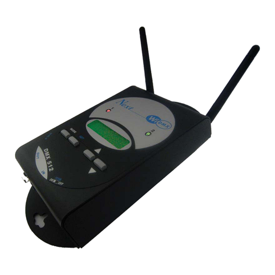
- Page 7 1.1 UNPACK WI-DMX Open the box; Remove the ac-adapter and the documentation. Take the equipment out of the box as shown in the picture below. 1.2 ACESSORIES AND DOCUMENTATION PROVIDED WITH THE EQUIPMENT Verify the contents of the packing. If one of the following parts of the packing is missing or damaged, please, contact your dealer immediately.
-
Page 8: Dmx Terminator
Standard DMX 512 signal INPUT with a 3/5-pole cannon connector. DMX TERMINATOR 2.2 MAKING A DMX 512 SIGNAL CABLE Wi DMX has a DMX 512 input/output that uses standard XLR 5-pin or XLR 3-pin connectors. The connection must be put into practice with shielded cable by these characteristics:... - Page 9 2.3 INPUT CONNECTION FOR POWER SUPPLY Plug the connector of the ac-adapter completly in the power input To disconnect it, extract gently. ATTENTION: do not use ac-adapters different from the one supplied, it could cause serious damages at the internal circuitation. 2.4 CONNECTION OF THE AC-ADAPTER TO THE MAIN AC MAKE SURE THAT VOLTAGE AND POWER FREQUENCY CORRESPOND TO WHAT IS REPORTED ON THE AC ADAPTER PLATE.
-
Page 10: Transmitter Mode
Confirm with SET key (Fig.2). 4.1 TRANSMITTER MODE This operation mode allows you to transmit the DMX 512 signal coming from a con- troller to the paired receivers, through two channels of transmission. The connection must be like in (Fig.4) - Page 11 To change the setting hold SET key (Fig.9) until the first value starts blinking (Fig.10). Use UP/DOWN keys to change the value (Fig.11). Fig. 7 Use MODE key to move to the next value (Fig.7). When finished, confirm with SET key (Fig.9) 1 - 48 C Fig. 8 1 48 C Fig.
- Page 12 To change the setting hold SET key (Fig.14) until the first value starts blinking (Fig.15). Use UP/DOWN keys to change the value (Fig.16). Fig. 12 Use MODE key to move to the next value (Fig.12). When finished, confirm with SET key (Fig.14) 49 - 128 C Fig. 13 49 128 C Fig.
- Page 13 4.6 RECEIVER PAIRING This function allows to pair the receiver Wi D Pen to the transmitter Wi DMX, to avoid interactions with other unit of the same type. With MODE key (Fig.17) find the text like in (Fig.18). MODE Connect Wi D Pen to the D D M M X X 5 5 1 1 2 2 t t r r a a n n s s m m i i t t t t e e r r signal I I N N (Fig.20/1) without connecting Wi D Pen ac-adapter.
-
Page 14: Receiver Mode
5.1 RECEIVER MODE This operation mode allows you to receive the DMX 512 signal coming from a Wi DMX transmitter and provide it to the connected projectors. The connection must be like in (Fig.23). Fig. 23 In this mode switch terminator to O O N N W i i D D M M X X receives the Radio signal and shows the number of channels generated (Fig.24);... - Page 15 5.2 STATE OF RX1 This function allows to visualize the state of the receiver of band 1. With MODE key (Fig.26) find the text like in (Fig.27). MODE 48ch C Reception OK Fig. 26 Fig. 27 no data C Reception OK no DMX signal Fig.
- Page 16 5.4 STATE OF RX2 This function allows to visualize the state of the receiver of band 2. With MODE key (Fig.28) find the text like in (Fig.29). MODE 128ch C Reception OK Fig. 28 Fig. 29 no data C Reception OK no DMX signal Fig.
- Page 17 5.6 PAIRING WITH TRANSMITTER (GET PAIRING) This function allows to pair the Wi DMX set as receiver with a Wi DMX set as trasmitter, to avoid interactions with other unit of the same type. For this operation you need a DMX signal cable connected between the two unit. MODE Remove any cable on the DMX connectors and connect the DMX signal cable between the two unit.
- Page 18 5.7 PAIRING WITH TRANSMITTER (GET PAIRING) USING WI D PEN This function allows to pair the Wi DMX set as receiver with a Wi DMX set as trasmitter. For this operation you need a Wi D PEN already paired with the trasmitter Wi DMX (v.par.4.6) With MODE key (Fig.37) find the text like in (Fig.38).
-
Page 19: Extender Mode
6.1 EXTENDER MODE This operation mode allows you to receive the DMX 512 signal coming from a Wi DMX transmitter, provide it to the connected projectors and re-transmit it to other receiver unit. The connection must be like in (Fig.43). - Page 20 6.2 SETTING OF TX1 This function allows to set the range of DMX channels to transmit on band 1 (RED LED) to the paired receivers and the RADIO channel to use, among the ten available (from 0R to 9R). With MODE key ( Fig.46) find the text like in ( Fig.47). MODE To change the setting hold SET key ( Fig.48) until the value starts blinking ( Fig.49).
- Page 21 6.4 SETTING OF RX2 This function allows to visualize the state of the receiver and to change the receiver band. With MODE key (Fig.51) find the text like in (Fig.52). To change the receiver band hold SET key (Fig.53) until the value changes (Fig.54).
- Page 22 7.1 TX BACKUP MODE TX BACKUP mode is intended for use as an immediate backup unit in case of failure during an event. This mode works exactly the same as TRANSMITTER mode, but data encoding is made using the key of another transmitter. In the event of faiure of the original transmitter, the unit set as TX BACKUP can generate the same signal as the original and then receiver will work without having to be paired again.
- Page 23 With a Wi-DPen receiver (this way you can clone a TX even AFTER it is dead...): Remove any DMX cable from Wi-DMX set as TX BACKUP Connect Wi-DPen to DMX-IN plug of Wi-DMX On Wi-DMX TX BACKUP, using MODE key (fig.56), find 'CLONE PAIRING' on display, then press SET for more than 2 seconds, PAIRING: READING...
- Page 24 Wi DMX TECHNICAL FEATURES Technical features: Signal Output signal: DMX512/ 1990 Input signal: DMX512/ 1990 Output connector: 3/5-pin cannon connector female Input connector: 3/5-pin cannon connector male Max number of projectors connected to the DMX output: 32 Technical features: Radio Frequency range: 2,4 GHz - 2,483 GHz (ISM) Number of channels: 20 Transmitter range: 1000 meters (3280 ft) open air...
Need help?
Do you have a question about the DMX 512 and is the answer not in the manual?
Questions and answers