Table of Contents
Advertisement
Advertisement
Table of Contents

Subscribe to Our Youtube Channel
Summary of Contents for Snap-On ETHOS
-
Page 1: User Manual
User Manual February 2009 ZEESC312J Rev. A... - Page 2 The information, specifications and illustrations in this manual are based on the latest information available at the time of printing. Snap-on reserves the right to make changes at any time without notice. Visit our Web site at: ethos.snapon.com (North America) snapondiag.com (Europe)
- Page 3 EC-DECLARATION OF CONFORMITY Snap-on Diagnostics a division of Snap-on UK Holdings Ltd. Denney Road, King's Lynn Norfolk, PE30 4HG England declare under our sole responsibility for design and manufacture that the following product, to which this declaration relates, is in conformity with the following European Directives:...
-
Page 4: Safety Information
Safety Information For your own safety and the safety of others, and to prevent damage to the equipment and vehicles upon which it is used, it is important that the accompanying Safety Information be read and understood by all persons operating, or coming into contact with, the equipment. We suggest you store a copy near the unit in sight of the operator This product is intended for use by properly trained and skilled professional automotive technicians. - Page 5 Safety Information Important Safety Instructions CAUTION Indicates a potentially hazardous situation which, if not avoided, may result in moderate or minor injury to the operator or to bystanders. Safety messages contain three different type styles. • Normal type states the hazard. Bold type states how to avoid the hazard.
-
Page 6: Table Of Contents
Contents Safety Information .......................iv Contents ..........................vi Chapter 1: Using This Manual ..................... 1 Conventions..........................1 Bold Text .......................... 1 Symbols ........................... 1 Terminology ........................1 Notes and Important Messages ..................2 Procedures........................2 Additional Manuals ......................... 2 Chapter 2: Introduction......................3 Functional Description ...................... -
Page 7: Contents
Contents Title Bar.......................... 16 Toolbar ........................... 17 Main Body ........................18 Making Selections ........................ 18 Screen Messages......................... 19 Loading and Connecting Messages................19 Confirmation Messages ....................19 Warning Messages ......................19 Error Messages......................19 Chapter 5: Operations......................20 Selecting from the Main Menu....................21 Identifying the Vehicle ...................... -
Page 8: Chapter 1 Using This Manual
Using This Manual Chapter 1 This manual contains tool usage instructions. Some of the illustrations shown in this manual may contain modules and optional equipment that are not included on your system. 1.1 Conventions The following conventions are used. 1.1.1 Bold Text Bold type is used in procedures to accent selectable items such as buttons and menu options. -
Page 9: Notes And Important Messages
Using This Manual Additional Manuals 1. Navigate to and highlight the Reset button. 2. Press the Y/a button. 1.1.4 Notes and Important Messages The following messages are used. Notes A NOTE provides helpful information such as additional explanations, tips, and comments. Example: NOTE: For additional information refer to... -
Page 10: Chapter 2 Introduction
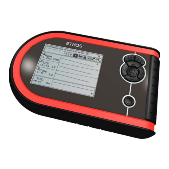
Introduction Chapter 2 The ETHOS™ (Figure 2-1) scan tool uses Vehicle Communication Software to provide vehicle-specific diagnostic trouble codes (DTCs) and datastream information for various vehicle control systems such as engine, transmission, antilock brake system (ABS) and more. Your scan tool can also graph live data parameters, record data, clear diagnostic trouble codes (DTCs) from the vehicle electronic control module (ECM) memory, and reset the vehicle malfunction indicator lamp (MIL). - Page 11 Introduction Functional Description Figure 2-2 ETHOS™ unit front view 1— Y/a (accept) button 2— S button 3— b (Up) button 4— N/x (back) button ® 5— CompactFlash card slot, under endgrip 6— c (Right) button 7— Power button 8— d (Down) button 9—...
-
Page 12: Technical Specifications
Introduction Technical Specifications Figure 2-4 ETHOS™ unit back view 1— Battery cover 2— Locking tabs 2.2 Technical Specifications Display: Light Emitting Diode (LED) backlight monochrome screen 320 x 240 resolution 4.7 inch (119.38 mm) diagonal Batteries: (6) 1.5V AA AC adapter: Input: 100–240V, 47–63 Hz... -
Page 13: Control Buttons
-4 to 149°F -20 to 65°C Data Buffer 240 data frames (values per parameter) Communication Protocols Your ETHOS scan tool supports the following OBD-II/EOBD communications protocols: SAE J1850 (VPW) SAE J1850 (PWM) ISO 9141-2 ISO 14230-4 (KWP 2000) ISO 15765-4 (CAN) In addition, the optional vehicle communications software allows you to access “enhanced”... -
Page 14: N/X (Back) Button
Introduction Connections 2.3.2 N/x (Back) Button The N/x button is used to do the following: • To exit a menu or program. • To close an open list and return to the previous menu. • To answer “No” when a Yes or No choice is given. •... -
Page 15: Dc Power Input
(CF) card slot, located under the handgrip, adds optional functionality to the scan tool. The ETHOS unit does not require a CF card to operate. The CF card slot on the scan tool is used for creating a backup file of the operating system and for accessing certain update functions. -
Page 16: Vehicle Power
Introduction Power Supply 2.5.1 Vehicle Power Vehicle power is required for the scan tool to properly communicate with the vehicle during testing. The 93L Data Cable (EAC0093L01A) provides 12V power to the unit through the vehicle data link connector (DLC). The scan tool turns on automatically whenever it is connected to a DLC that provides power. -
Page 17: Data Cable
Introduction 93L Data Cable For related information, see the following sections: “DC Power Input” on page 8 • • “Connecting the AC/DC Power Supply” on page 14 2.6 93L Data Cable An 93L Data Cable (Figure 2-6) is included with your scan tool. The data cable plugs directly into the 16-pin data link connector (DLC) on OBD-II vehicles. -
Page 18: Chapter 3 Getting Started
The scan tool comes with six alkaline AA batteries. Rechargeable nickel-metal hydride (NiMH) batteries may also be used. Do not use standard (lead/zinc) batteries as they do not provide sufficient power to operate the scan tool, and may leak and damage your ETHOS™. For related information, see the following sections: •... -
Page 19: Connecting To Vehicle Power
Getting Started Connecting to Vehicle Power Figure 3-1 ETHOS™ battery polarity 4. Replace the battery cover. Note the following safety warnings when installing batteries. WARNING Risk of personal injury or harm. • Always make sure the battery polarities (“+” and “–”) are correct when installing. - Page 20 Disconnect the data cable from the connector saver, but do not remove the connector saver from the scan tool. Figure 3-2 Data cable connections 1— Ethos unit 2— Connector saver 3— 93L Data cable 2. Attach the 25-pin connector of the 93L Data Cable to the connector saver (Figure 3-2).
-
Page 21: Connecting The Ac/Dc Power Supply
3.6 Selecting a Language NOTE: This Selecting a Language section applies to units sold in North America only. English is the default language selection in the ETHOS software. However, you can change the language setting if desired. To change the language setting: 1. -
Page 22: Powering Off The Unit
Getting Started Powering Off the Unit 3.7 Powering Off the Unit Use the Power button (Figure 2-2 on page 4) to turn the scan tool off. To power the unit off: 1. Navigate to a menu. 2. Press the Power button. The Shut Down System dialog box displays (Figure 3-3). -
Page 23: Chapter 4: Navigation
Navigation Chapter 4 The following sections describe screen layout, how to navigate the interface, and how to make selections using screen menus and buttons. The various types of ETHOS™ screen messages are also explained in this section. 4.1 Screen Layout Scan tool screens (Figure 4-1) typically include the following sections: •... -
Page 24: Toolbar
Navigation Screen Layout Definitions of title bar icons are shown in Table 4-1. Table 4-1 Title bar icon definitions TYPE ICON DEFINITION Indicates power is being supplied by the internal batteries Indicates the internal batteries are weak and need replacement Power source Indicates power is being supplied by the AC/DC power supply... -
Page 25: Main Body
Navigation Making Selections Table 4-2 Data toolbar buttons (part 2 of 2) BUTTON ICON FUNCTION Moves forward one frame when Next Frame viewing recorded or paused data When collecting data, indicates the Record data being displayed is paused and not being updated Lets you selects which parameters to Custom Data List... -
Page 26: Screen Messages
Navigation Screen Messages To make selections: 1. Highlight a button or menu option. 2. Press Y/a to confirm the selection. NOTE: Menus that only list one item require a press of the Y/a button to advance. 4.3 Screen Messages There are four types of on-screen messages: •... -
Page 27: Chapter 5: Operations
Operations Chapter 5 This section explains general ETHOS™ scan tool operations and offers instructions for customizing certain functions. The following is an outline of basic scan tool operations for testing a vehicle. NOTE: The sequence of steps and the menu selections may vary depending upon the make or model of the test vehicle. -
Page 28: Selecting From The Main Menu
Asian Vehicles European Vehicles Tools Figure 5-2 Sample ETHOS™ unit main menu The software selection screen also offers these options: Last Vehicle—resets the ID to the last vehicle tested. See “Main Menu Identification • Options” on page 22 for details. -
Page 29: Main Menu Identification Options
Operations Identifying the Vehicle NOTE: The identification procedure varies by manufacturer. See the appropriate Vehicle Communication Software Manual for details. To identify a vehicle: 1. From the Software Confirmation screen, press Y/a. The initial vehicle identification (ID) process begins (Figure 5-3). Mercedes Select 10th VIN Character 5 - 2005... -
Page 30: Selecting A System
Operations Selecting a System Previous Vehicles and Data Last 20 Restore Delete 2004 (10th VIN = 4) S80 2.3L 5CYL TURBO ... 2002 210 (E-SERIES) 210.065 (E-SERIES) ... 2004 HONDA CIVI 1.6L D16V 2000 HONDA S200 2.0L F20C 2001 (10th VIN = 1) NEW BEETLE 1.6 MPI ... 1999 5-SERIES [E39] 2.8L 24V MPI CAT =... -
Page 31: Connecting To A Vehicle
Connection instructions prompt you to connect the scan tool to a vehicle data link connector (DLC) for testing (Figure 5-7). See the appropriate vehicle communication software manual for details on connecting to a vehicle. * * * * ETHOS* * * * Connect: 93L Cable. Location: Under left side of dash. -
Page 32: Selecting From The Vehicle Menu
Operations Selecting from the Vehicle Menu 5.5 Selecting from the Vehicle Menu Depending on the make and model, a number of options may be available (Figure 5-8)..2.5L 24V MPI CAT = 256S5 Main Menu Codes Only Data Only Functional Tests Service Reset Stop Communication... -
Page 33: Data Display
Operations Selecting from the Vehicle Menu ... 2004 3.8L V6 ... Codes Menu Trouble Codes Clear Codes Freeze Frame/Failure Records DTC Status Figure 5-9 Sample codes submenu 5.5.2 Data Display Select Data Display to view live datastream parameters from the vehicle ECM (Figure 5-10). 1411 TPS(%) TPS(V) - Page 34 Operations Selecting from the Vehicle Menu ST TRIM-1(%) O2 B1-S1(mV) INJ PW B1(mS) 19.3 ST TRIM-1(%) O2 B2-S1(mV) O2 B1-S2(mV) O2 B2-S2(mV) INJ PW B1(mS) 19.3 INJ PW B2(mS) 14.0 ST TRIM-1(%) Figure 5-11 Sample data display screen 1— Upper frame (locked parameters) 2—...
- Page 35 Operations Selecting from the Vehicle Menu 2. Scroll to review the data in the frame. 3. To switch frames, Highlight Previous Frame or Next Frame, then press Y/a. Each button push moves one frame in the selected direction. To resume collecting data: Select Record.
-
Page 36: Changing Screen Views
Operations Selecting from the Vehicle Menu TPS(%) TPS(V) O2 B1-S1(mV) O2 B2-S1(mV) O2 B1-S2(mV) O2 B2-S2(mV) INJ PW B1(mS) INJ PW B2(mS) Figure 5-14 Sample data selection screen 2. Highlight a button on the Custom Data List toolbar. Use the left (e) and right (c) arrows to move between buttons. Button Description Select/Deselect, use to mark individual... -
Page 37: Locking Parameters
Operations Selecting from the Vehicle Menu 3001 755-3238 TPS(%) 0-98 TPS(V) 0.00 0.00-3.55 02 B1S1(m 52-911 Figure 5-15 Sample Graph view screen Any previously set conditions, such as held data or locked lines of data, remain in effect when the screen view is changed. To change the screen view: •... - Page 38 • A save movie dialog box displays while data is being saved (Figure 5-17). The movie is saved when the message box disappears. * * * * ETHOS* * * * Saving the Movie. Figure 5-17 Sample Save Movie dialog box The S button can be programmed to perform the Save Screen or Save Movie function.
-
Page 39: Generic Functions
The S button can be programmed to perform print functions, Print Screen or Print Page. See “S Button” on page 33 for details. Tools The Tools button is a shortcut, it is the same as selecting Tools from the ETHOS main menu. See “Using Tools” on page 33 for details. 5.5.3 Generic Functions Select Generic Functions from a VIN-specific menu and a submenu of OBD-II tests displays (Figure 5-18). -
Page 40: Using Tools
Operations Using Tools 5.6 Using Tools The Tools button provides access to system information and various system controls. The tools options are discussed in the following sections: “S Button” on page 33 • • “Units” on page 34 • “Setup” on page 34 •... -
Page 41: Units
Operations Using Tools 5.6.2 Units Select Units to choose between US customary or metric units of measure for certain data parameters. Table 5-1 Units of measurement—defaults and options SETTING DEFAULT OPTION Temperature degrees Celsius (°C) degrees Fahrenheit (°F) Air Pressure (including manifold kilopascals (kPa) inches of mercury (“Hg) -
Page 42: Sys (System Information)
The Sys selection lets you view your scan tool configuration information (Figure 5-21). Tools Menu Units Setup ETHOS Copyright 2008 Snap-on Incorporated. All Rights Reserved. ETHOS is a trademark of Snap-on Incorporated. Patents US B15,442,170; AU 630,261; US 6,693,367; Patents Pending 09/09/2008 08:40 Bundle 8.4 Version 1.5.0.4883... -
Page 43: Backup To Cf
Recording and Viewing Movies 5.6.6 Backup to CF Select Backup to CF to save a backup copy of the ETHOS™ programming and saved data to a CompactFlash® (CF) card. Follow the screen instructions to create a backup CF. See “Making a Backup CompactFlash® (CF) Card” on page 41for additional information. - Page 44 Operations Service Menu IMPORTANT: IMPORTANT: Improper use of Service Menu items can corrupt the internal file structure and render the scan tool inoperative. To open the Service Menu: 1. Simultaneously hold down the Y/a and N/x buttons. 2. Press the Power button to open the Service Menu. The Service menu displays.
-
Page 45: Chapter 6 Maintenance
6.2 Display Window Replacement Use the optional Display Window Kit to replace the hard plastic faceplate of the Ethos unit. Thoroughly clean the scan tool first, and work carefully to keep dirt out of the unit during window replacement. -
Page 46: Replacing The Batteries
(NiMH) type AA batteries only. Do not use standard (lead/zinc) batteries as they do not provide sufficient power to operate the scan tool, and may leak and damage your ETHOS™. Use the following procedure when replacing batteries in your scan tool. -
Page 47: Disposing Of The Batteries
Maintenance Storage Tips To replace the batteries: 1. Depress the two battery cover lock tabs and lift off the battery cover (Figure 6-3). Figure 6-3 Battery cover lock tabs 1— Battery cover 2— Lock tabs 2. Remove the old batteries. 3. -
Page 48: Making A Backup Compactflash® (Cf) Card
6.5 Making a Backup CompactFlash® (CF) Card As a preventive measure, it is always a good idea to create a backup of the ETHOS™ programming on a (CF) card. The CF can be used to restore the scan tool in the event of a catastrophic failure. -
Page 49: Updating From A Compactflash® (Cf) Card
5. Select Tools > Disk Utilities from the menu. 6. Scroll down to read the entire message. The version of the software currently installed on your ETHOS™ displays at the bottom of the screen. 7. When prompted, press Y/a to read the software version on the CF. -
Page 50: Appendix A: Troubleshooting
Troubleshooting Appendix A This section addresses issues that may arise when using the ETHOS™ scan tool. A.1 Bent Cable Connector Pin The contact pins of the data cable connector saver may break or become bent. Bent pins make it difficult or impossible to connect the cable, and missing pin cause communication problems. -
Page 51: Cannot Access The Compactflash® (Cf) Card
See “Powering Off the Unit” on page 15. A.7 Restarting the Unit If your ETHOS™ freezes or will not power off, you can restart the unit as follows: To perform a restart: 1. Disconnect the data cable, and disconnect the AC/DC power supply, if in use 2. -
Page 52: Index
Index AC/DC power supply, 8, 9, 14 Pausing data, 27 Power button, 7 Power supply, 8–10, 11 Powering off, 15 Batteries Powering on, 14 Installing, 11–12 Previous vehicles and data, 21 Replacing, 39 Printing, 32, 34 Buttons Control, 4, 6–7 Toolbar, 17, 33–36 Restarting, 44 Cable connections, 4, 7...
Need help?
Do you have a question about the ETHOS and is the answer not in the manual?
Questions and answers