Table of Contents
Advertisement
Quick Links
2
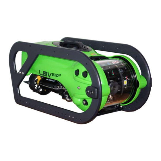
LBV200
Operators Manual
DOCS-010
Rev B
The information, photographs, illustrations and descriptions contained in this manual are the
property of SeaBotix Inc. Unauthorized duplication and distribution is strictly forbidden.
Additionally, SeaBotix Inc. reserves the right to alter any and all information contained in this
manual.
Head Office: SeaBotix Inc., 2877 Historic Decatur Road STE 100, San Diego, CA 92106 USA +1 (619) 450-4000
Australia Office: SeaBotix Inc. Australia Pty Ltd.8A Sparks Road, Henderson, WA 6166, Australia +61 (0)8 9437-5400
© 2009 by SeaBotix, Inc. All Rights Reserved
Advertisement
Table of Contents
Troubleshooting

Related Manuals for SeaBotix LBV2002

Summary of Contents for SeaBotix LBV2002
- Page 1 Additionally, SeaBotix Inc. reserves the right to alter any and all information contained in this manual. Head Office: SeaBotix Inc., 2877 Historic Decatur Road STE 100, San Diego, CA 92106 USA +1 (619) 450-4000 Australia Office: SeaBotix Inc. Australia Pty Ltd.8A Sparks Road, Henderson, WA 6166, Australia +61 (0)8 9437-5400...
-
Page 2: Table Of Contents
Trim .........................19 2.1.5.2 Head .......................20 2.1.5.3 Depth ......................20 2.1.7 Power ......................20 2.1.8 Auxiliary ......................20 2.1.9 Position ......................20 2.1.10 Thruster Gain ....................20 DOCS-010 Manual, SeaBotix Inc. Users, 200 Series – 18 Mar 09 - Rev B - Page 2 of 52... - Page 3 Practice ......................32 3.5.1 Watching the LBV ...................32 3.5.2 Watching the monitor ..................32 Controlling the LBV ..................33 Thruster Gain Control ..................33 Trim .........................33 DOCS-010 Manual, SeaBotix Inc. Users, 200 Series – 18 Mar 09 - Rev B - Page 3 of 52...
- Page 4 Proper Operating Conditions ................44 Fault Modes ....................45 Glossary of Abbreviations .....................48 Warranty ........................51 Limitations and Exclusions ....................51 Shipping Charges ......................51 Return Policy ........................52 DOCS-010 Manual, SeaBotix Inc. Users, 200 Series – 18 Mar 09 - Rev B - Page 4 of 52...
- Page 5 LBV system that has been altered or modified without the prior written consent from SeaBotix Inc. DOCS-010 Manual, SeaBotix Inc. Users, 200 Series – 18 Mar 09 - Rev B - Page 5 of 52...
- Page 6 SeaBotix Inc., reserves the right to make changes to the specifications of the LBV and/or alter any documentation at any time, without notice. DOCS-010 Manual, SeaBotix Inc. Users, 200 Series – 18 Mar 09 - Rev B - Page 6 of 52...
-
Page 7: Section 1. Introduction
Note: When unpacking the LBV after receipt, inspect the LBV for damage. It is strongly recommended that vacuum be verified before each use (see section 1.4.1). DOCS-010 Manual, SeaBotix Inc. Users, 200 Series – 18 Mar 09 - Rev B - Page 7 of 52... -
Page 8: Power Requirements
LBV systems fitted with the HPDC1502 Brush-Less DC Thrusters have a requirement for 1,200 watts 100-130/200-250 VAC, 50/60 Hz. DOCS-010 Manual, SeaBotix Inc. Users, 200 Series – 18 Mar 09 - Rev B - Page 8 of 52... -
Page 9: Setting Up The System
Open the shackle completely. Note: There is an indent to allow the locking rod to be flush with the “D” portion of the shackle. DOCS-010 Manual, SeaBotix Inc. Users, 200 Series – 18 Mar 09 - Rev B - Page 9 of 52... - Page 10 Once the tether is connected to the LBV, the next step is to connect the Integrated Control Console/Surface Power Supply. Again, ensure that the Integrated Control Console/Surface Power Supply is OFF. DOCS-010 Manual, SeaBotix Inc. Users, 200 Series – 18 Mar 09 - Rev B - Page 10 of 52...
-
Page 11: 1.3.2 Integrated Control Console
„Video In‟ BNC jack on the ICC. The Video Out is used for additional display or recording devices. CBA066 Video Cable Reel Video Output Jack ICC Video In & Video Out DOCS-010 Manual, SeaBotix Inc. Users, 200 Series – 18 Mar 09 - Rev B - Page 11 of 52... -
Page 12: Pre-Dive Inspection And System Test
3. Check the thrusters for objects that may get or be caught in the propellers. 4. Check vacuum before every dive. DOCS-010 Manual, SeaBotix Inc. Users, 200 Series – 18 Mar 09 - Rev B - Page 12 of 52... - Page 13 Insert and tighten the Phillips pan head seal screw into the check valve. CAUTION: Do not over tighten the seal screw as it could damage the sealing o-ring. DOCS-010 Manual, SeaBotix Inc. Users, 200 Series – 18 Mar 09 - Rev B - Page 13 of 52...
-
Page 14: Powering Up The System
4. Press the LIGHT key to turn light on the internal light. 5. Press + and – to vary the light intensity a. Repeat with the second camera; if fitted with light. DOCS-010 Manual, SeaBotix Inc. Users, 200 Series – 18 Mar 09 - Rev B - Page 14 of 52... -
Page 15: Video Overlay
Place the OCU in a carrying/shipping case. Place the tether in a carrying/shipping case. Close and clamp cases for transport or storage. DOCS-010 Manual, SeaBotix Inc. Users, 200 Series – 18 Mar 09 - Rev B - Page 15 of 52... -
Page 16: Trimming Rov
LBV is properly set up left to right and fore to aft. DOCS-010 Manual, SeaBotix Inc. Users, 200 Series – 18 Mar 09 - Rev B - Page 16 of 52... -
Page 17: Calibrating Compass
LBV, spend time with the LBV at the surface where you can see how the commands affect the LBV. DOCS-010 Manual, SeaBotix Inc. Users, 200 Series – 18 Mar 09 - Rev B - Page 17 of 52... -
Page 18: Joystick
If a light accompanies the optional second camera, the light controls will also switch. DOCS-010 Manual, SeaBotix Inc. Users, 200 Series – 18 Mar 09 - Rev B - Page 18 of 52... -
Page 19: Tilt
TRIM button. Press the TRIM button again to DOCS-010 Manual, SeaBotix Inc. Users, 200 Series – 18 Mar 09 - Rev B - Page 19 of 52... -
Page 20: Head
(see section 2.2 Video Overlay for more information). 2.1.10 Thruster Gain 2.1.10.1 Vertical Thruster Gain DOCS-010 Manual, SeaBotix Inc. Users, 200 Series – 18 Mar 09 - Rev B - Page 20 of 52... -
Page 21: Horizontal Thruster Gain
The Video Overlay can be manipulated to display the information in a manner that best suits the user. Video Overlay 1. User Text (Displays at Top) 7. Date DOCS-010 Manual, SeaBotix Inc. Users, 200 Series – 18 Mar 09 - Rev B - Page 21 of 52... -
Page 22: User Text
–90 indicates that the camera is pointing straight down. The value displayed always represents the camera currently being used. DOCS-010 Manual, SeaBotix Inc. Users, 200 Series – 18 Mar 09 - Rev B - Page 22 of 52... -
Page 23: Time And Date
Pressing the 3 key will enable the Accessory + and – keys to operate an optional accessory. Same as 1. and 2. 4. Acc. Not Found DOCS-010 Manual, SeaBotix Inc. Users, 200 Series – 18 Mar 09 - Rev B - Page 23 of 52... -
Page 24: Main Menu
3. Select the month of the year by pressing the number corresponding to the month by using the keypad. For example, if the month is March press 0 then 3. 4. Press ENT DOCS-010 Manual, SeaBotix Inc. Users, 200 Series – 18 Mar 09 - Rev B - Page 24 of 52... -
Page 25: Units/Water Type
To clear the user text from the Setup Menu (see section 2.3.3), press 4 to start entering user text. Then press the # key followed by the * key. DOCS-010 Manual, SeaBotix Inc. Users, 200 Series – 18 Mar 09 - Rev B - Page 25 of 52... -
Page 26: Reset To Defaults
Press key 1 to increase the value Press key 2 to decrease the value Press key 3 to reset the value DOCS-010 Manual, SeaBotix Inc. Users, 200 Series – 18 Mar 09 - Rev B - Page 26 of 52... -
Page 27: Depth
Pressing the 2 key will allow you to view the current software versions. This information is important when technical assistance is required. – Operator Control Unit (OCU) – Flash in LBV (Operational Program) DOCS-010 Manual, SeaBotix Inc. Users, 200 Series – 18 Mar 09 - Rev B - Page 27 of 52... -
Page 28: Hours Run
Pressing the 4 key will allow the user to reverse the operation of the vertical thruster knob on the Operator Control Unit. DOCS-010 Manual, SeaBotix Inc. Users, 200 Series – 18 Mar 09 - Rev B - Page 28 of 52... - Page 29 System Diagnostic See section 2.3.5.1 Software Version Hours Run Display Internal Temp Camera Rotate Options Audio Channel Camera Tilt Vert. Thruster DOCS-010 Manual, SeaBotix Inc. Users, 200 Series – 18 Mar 09 - Rev B - Page 29 of 52...
-
Page 30: Section 3. Operating The Lbv
Safe to Grab NOTE: When deploying the LBV, ensure that there is a clear path for the tether to deploy out. DOCS-010 Manual, SeaBotix Inc. Users, 200 Series – 18 Mar 09 - Rev B - Page 30 of 52... -
Page 31: Tether
LBV maintains desired depth without constant input from the user. Auto heading LBV maintains desired heading without constant input from the DOCS-010 Manual, SeaBotix Inc. Users, 200 Series – 18 Mar 09 - Rev B - Page 31 of 52... -
Page 32: Practice
Here are some skills to practice: Forward, reverse, lateral, rotate, dive and surface Gain control of thrusters Trim Heading Depth Camera rotate Auto functions Overlay position DOCS-010 Manual, SeaBotix Inc. Users, 200 Series – 18 Mar 09 - Rev B - Page 32 of 52... -
Page 33: Controlling The Lbv
The LBV will continue to dive until the trim key is pressed again. DOCS-010 Manual, SeaBotix Inc. Users, 200 Series – 18 Mar 09 - Rev B - Page 33 of 52... -
Page 34: Auto Functions
LBV and reduce maintenance. Performing the basic care as listed in this section will provide you with years of use and enjoyment. After each use DOCS-010 Manual, SeaBotix Inc. Users, 200 Series – 18 Mar 09 - Rev B - Page 34 of 52... -
Page 35: After Each Use - Dirty Water Conditions
LBV handle. TO005 required. Step 4 Place the LBV on its side. DOCS-010 Manual, SeaBotix Inc. Users, 200 Series – 18 Mar 09 - Rev B - Page 35 of 52... - Page 36 LBV itself. Step 10 Remove the four M6 x 20 button head screws securing the bumper frame to the shell. TO005 Required. DOCS-010 Manual, SeaBotix Inc. Users, 200 Series – 18 Mar 09 - Rev B - Page 36 of 52...
- Page 37 Remove the two M4 x 20 Phillips head screws securing the shell to the float. TO015 Required. Step 17 Remove the shell. DOCS-010 Manual, SeaBotix Inc. Users, 200 Series – 18 Mar 09 - Rev B - Page 37 of 52...
- Page 38 Soak the LBV in a container of fresh water or, use a hose with a low velocity nozzle to rinse the LBV thoroughly. DOCS-010 Manual, SeaBotix Inc. Users, 200 Series – 18 Mar 09 - Rev B - Page 38 of 52...
-
Page 39: Every 50 Hours
Step 6 Remove the two M6 x 16 button head screws securing the front of the float to the backplane. DOCS-010 Manual, SeaBotix Inc. Users, 200 Series – 18 Mar 09 - Rev B - Page 39 of 52... - Page 40 Step 14 Repeat steps 11, 12 and 13 for each thruster. DOCS-010 Manual, SeaBotix Inc. Users, 200 Series – 18 Mar 09 - Rev B - Page 40 of 52...
-
Page 41: Every 500 Hours
500 hour maintenance is performed. There may be a need to replace the view port if it is scratched excessively. Replacement of some fasteners may be required as they may corrode with time. DOCS-010 Manual, SeaBotix Inc. Users, 200 Series – 18 Mar 09 - Rev B - Page 41 of 52... -
Page 42: Repairs
On most LBV‟s (PAL or NTSC), the video output is composite video which is then converted to fiber optic data inside the splice in the tether. DOCS-010 Manual, SeaBotix Inc. Users, 200 Series – 18 Mar 09 - Rev B - Page 42 of 52... -
Page 43: Troubleshooting Aids
Please remember that at no time should any component be plugged in or unplugged while the SPS, ICC or LBV is energized during fault diagnosis. DOCS-010 Manual, SeaBotix Inc. Users, 200 Series – 18 Mar 09 - Rev B - Page 43 of 52... -
Page 44: Proper Operating Conditions
-Upon energizing the SPS main power switch, the SPS red and amber LEDs are continuously lit and do not flash. The LBV is not energized and the LBV does not output video. DOCS-010 Manual, SeaBotix Inc. Users, 200 Series – 18 Mar 09 - Rev B - Page 44 of 52... -
Page 45: Fault Modes
LBV end of the tether (between pins 1 & 3) are more than 0, but less than 300 VDC. The LBV Motherboard power LEDs are continuously unlit. DOCS-010 Manual, SeaBotix Inc. Users, 200 Series – 18 Mar 09 - Rev B - Page 45 of 52... - Page 46 LBV150 (300, 600) is displayed. Normal or slightly corrupted overlay data is then shown. Fault: The thruster is drawing excessive current when thrusting. DOCS-010 Manual, SeaBotix Inc. Users, 200 Series – 18 Mar 09 - Rev B - Page 46 of 52...
- Page 47 For additional troubleshooting steps please refer to our website: http://www.seabotix.com/support/troubleshooting.htm For further support, please contact us either by phone or email at: http://www.seabotix.com/support/service.htm DOCS-010 Manual, SeaBotix Inc. Users, 200 Series – 18 Mar 09 - Rev B - Page 47 of 52...
-
Page 48: Glossary Of Abbreviations
LBV and video display only! It has external data connections for exporting SONAR and tracking to a separate display device. DOCS-010 Manual, SeaBotix Inc. Users, 200 Series – 18 Mar 09 - Rev B - Page 48 of 52... - Page 49 Standard Brushed Thruster Surface Power Supply. Converts supply AC power to DC at ~360 VDC for transfer to the LBV via the tether. DOCS-010 Manual, SeaBotix Inc. Users, 200 Series – 18 Mar 09 - Rev B - Page 49 of 52...
- Page 50 LBV onto the monitor. Vehicle Power Supply. Converts the ~360 VDC tether supply voltage to the 28 VDC required for LBV operation. DOCS-010 Manual, SeaBotix Inc. Users, 200 Series – 18 Mar 09 - Rev B - Page 50 of 52...
-
Page 51: Warranty
SeaBotix Inc. warranty center. Warranty centers are located around the world to help reduce transit time and distance required for warranty repairs or service. DOCS-010 Manual, SeaBotix Inc. Users, 200 Series – 18 Mar 09 - Rev B - Page 51 of 52... -
Page 52: Return Policy
Upon receipt of the returned merchandise in good order, and in accordance with the above provisions, SeaBotix Inc. will promptly refund your purchase price. DOCS-010 Manual, SeaBotix Inc. Users, 200 Series – 18 Mar 09 - Rev B - Page 52 of 52...
Need help?
Do you have a question about the LBV2002 and is the answer not in the manual?
Questions and answers