Table of Contents
Advertisement
Installation & Service Instructions
Inset Decorative Gas Fire for use with the
THE GAS SAFETY (INSTALLATION AND USE) REGULATIONS 1994.
''In your own interest, and that of safety, it is law that all gas appliances are installed by competent persons,
in accordance with the above regulations. Failure to install appliances correctly could lead to prosecution.''
The polythene bags used for packaging are a potential hazard to babies and young children
LEAVE THESE INSTRUCTIONS WITH THE USER FOR USE ON FUTURE CALLS
For Use With Natural Gas
(G20) Only At 20mbar
For Use in GB & IE
Potterton Housewarmer 45 & 55 BBu's
and MUST BE DISPOSED OF IMMEDIATELY.
Potterton Housewarmer Illusion ASD - G.C. NO. 37 590 16
966 Inset DGF with ILLUSION FACIA
Potterton Housewarmer Stratton ASD - G.C. NO. 37 590 17
966 Inset DGF with STRATTON FACIA
Potterton Housewarmer Presence ASD - G.C. NO. 37 590 18
966 Inset DGF with PRESENCE FACIA
IMPORTANT
PLEASE READ THIS BOOK
BEFORE INSTALLING,
OPERATING OR
SERVICING THIS
APPLIANCE.
Part No. 966/9350/1 – 02
Advertisement
Table of Contents

Subscribe to Our Youtube Channel
Summary of Contents for Potterton Illusion
- Page 1 Part No. 966/9350/1 – 02 Potterton Housewarmer Illusion ASD - G.C. NO. 37 590 16 966 Inset DGF with ILLUSION FACIA Potterton Housewarmer Stratton ASD - G.C. NO. 37 590 17 966 Inset DGF with STRATTON FACIA Potterton Housewarmer Presence ASD - G.C. NO. 37 590 18 966 Inset DGF with PRESENCE FACIA Installation &...
-
Page 2: Table Of Contents
11.4 Lint Trap.................................. 16 11.5 Piezo Unit ................................16 11.6 Gas Tap.................................. 17 12. Short List of Spares................................ 19 If you have any problems or questions concerning this appliance, please contact the Potterton Myson Technical Help Line - Telephone (01926) 410044. -
Page 3: Technical Data
1. Technical Data - Page 3 Illusion Stratton Presence Weight - Packed - Fire 23.90kg (52.7lb). 23.90kg (52.7lb). 23.90kg (52.7lb). Weight - Unpacked - Fire 18.98kg (41.8lb). 18.98kg (41.8lb). 18.98kg (41.8lb). Weight - Packed - Facia 21.25kg (46.8lb). 17.00kg (37.5lb). -
Page 4: General
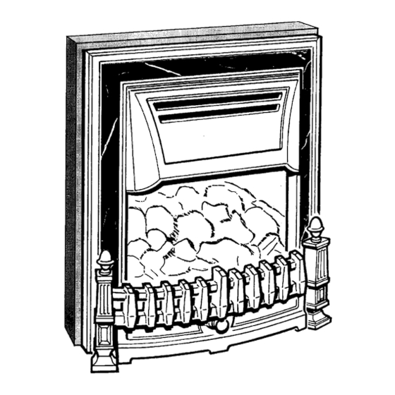
The 966 is an inset decorative gas fire. It is lit by a piezo spark igniter so batteries or electricity are not required. When fitted with either the Illusion, Stratton or Presence Facia, this fire is only suitable for use with the Potterton Housewarmer 45 & 55 BBu's. -
Page 5: Hearths, Walls, Fire Surrounds, Shelves & Clearances
General - Page 5 3.2. Hearths, Walls, Fire Surrounds, Shelves & Clearances. Hearths The fire MUST be installed onto a non-combustible hearth. The hearth must be to the dimensions shown in Fig. 2. Walls If the wall against which the fire is to be mounted has a combustible cladding or surround, the following conditions must be met:- 1. -
Page 6: Installation
4. Installation - Page 6 4.1. Unpack the Fire The fire is supplied in 2 packs. Pack 2 of 2 contains:- The Convector Box. Burner Tray. Spillage Plate. Outer Metal Surround. Ceramics Pack. Control Board Mounting Bracket. Bag of Fittings. Poly Bag containing these Instructions and other literature. -
Page 7: Prepare The Fire
Installation - Page 7... -
Page 8: Install The Convector Box, Blanking Panel & Burner Tray
Installation - Page 8... -
Page 9: Burner Tray & Gas Supply
Installation - Page 9 4.4. Install the Convector Box a) Attach the self adhesive foam strip along the sides and top of the outer edge of the convector box at the rear. b) Hook the spillage plate over the top edge of the firebox as shown in figure 6 and secure using the 2 No.6 x 9.5mm screws from the bag of fittings. -
Page 10: Check Gas Pressure & Operation Of The Fire
6. Check Gas Pressure & Operation Of Fire - Page 10 The test point screw is located on the left hand side of the controls assembly near the gas tap. a) Remove the pressure test point screw and connect a pressure gauge. b) Push in and turn the control knob anti-clockwise to the ' ' (ignition/pilot) setting and the pilot should... -
Page 11: Fitting The Facia
8. Fitting The Facia - Page 11 a) Loosen the 2 facia fixing bracket screws (1 each side) located at the bottom of the convector box and slide the brackets towards the centre of the appliance. Temporarily re-tighten the screws. b) Lift the facia and position it centrally on the convector box ensuring that the 2 lugs at the top of the facia locate in the 2 holes at the top of the convector box. -
Page 12: Complete The Installation
9. Complete The Installation - Page 12 Locate the Plinth into position at the front of the appliance. In the interests of hygiene please wash your hands on completion of the installation. Leave the bag of vermiculite with the consumer to allow them to top up the burner tray. -
Page 13: Servicing & Cleaning
10 Servicing & Cleaning - Page 13 Refer to the separate boiler instructions supplied with the boiler for cleaning the boiler. To ensure continued efficient operation of the appliance, it is recommended that it is checked and cleaned as necessary at regular intervals. -
Page 14: Replacement Of Parts
11. Replacement of Parts - Page 14 11.1. General Access a) Carefully pull the plinth away from the fire. b) Remove the facia (2) by slackening off or removing the facia fixing brackets at the base of the facia. Lift the facia off the convector box. -
Page 15: Pilot Burner Assembly
Replacement of Parts - Page 15 c) Close the gas fire isolation tap and undo the union. d) Loosen the 2 wing nuts securing the burner tray to the convector box, then carefully remove the burner tray. e) To avoid accidental spillage, carefully empty the vermiculite (Ash Effect) out of the burner tray into a suitable container and put somewhere safe. -
Page 16: Burner Injector
Replacement of Parts - Page 16 11.3. Burner Injector a) Perform General Access - 11.1. b) Disconnect the union nut securing the pipe to the injector carrier. c) Remove the screw securing the injector carrier to the injector box then carefully withdraw the injector carrier. d) Unscrew injector from the injector carrier. -
Page 17: Gas Tap
Replacement of Parts - Page 17 11.6. Gas Tap a) Perform General Access - 11.1. b) Pull the control knob off the gas tap. c) Remove the 2 screws securing the bezel around the tap. Remove the bezel. d) Pull the electrode lead off the piezo unit. e) Unscrew the thermocouple from the rear of the gas tap. -
Page 18: Short List Of Spares
12. Short List Of Spares - Page 18 Drg. G.C. Description Makers Ref. Part No. 389 583 Burner Injector - Bray CAT 28/340 966/705 158 582 Tap Assembly - Includes Drg. Ref. 3 364/1044 385 855 Piezo Unit 942/9387 127 293 Pilot Burner Assembly (Atmospheric Sensing Device) 960/1433 127 022...
Need help?
Do you have a question about the Illusion and is the answer not in the manual?
Questions and answers