Table of Contents
Advertisement
Quick Links
Installation and Operation Instructions
Installation and Operation
Instructions for
Pennant
Hydronic Boiler
Model PNCH
Water Heater
Model PNCV
Sizes 200, 300, 400
This product must be installed and serviced by a professional service technician,
FOR YOUR SAFETY:
qualified in hot water boiler installation and maintenance. Improper installation and/or operation could
create carbon monoxide gas in flue gases which could cause serious injury, property damage, or
death. Improper installation and/or operation will void the warranty. For indoor installations, as an
additional measure of safety, Laars strongly recommends installation of suitable Carbon Monoxide
detectors in the vicinity of this appliance and in any adjacent occupied spaces.
WARNING
If the information in this manual is not
followed exactly, a fire or explosion may
result causing property damage, personal
injury or loss of life.
Do not store or use gasoline or other
flammable vapors and liquids in the vicinity of
this or any other appliance.
WHAT TO DO IF YOU SMELL GAS
• Do not try to light any appliance.
• Do not touch any electrical switch; do not
use any phone in your building.
• Immediately call your gas supplier from
a nearby phone. Follow the gas supplier's
instructions.
• If you cannot reach your gas supplier, call
the fire department.
Installation and service must be performed
by a qualified installer, service agency, or gas
supplier.
™
Heating Systems Company
A subsidiary of
BRADFORD WHITE
AVERTISSEMENT
Assurez-vous de bien suivres les instructions
données dans cette notice pour réduire au
minimum le risque d'incendie ou d'explosion ou
pour éviter tout dommage matériel, toute blessure
ou la mort.
Ne pas entreposer ni utiliser d'essence ni d'autres
vapeurs ou liquides inflammables dans le voisinage
de cet appareil ou de tout autre appareil.
QUE FAIRE SI VOUS SENTEZ UNE ODEUR DE GAZ:
• Ne pas tenter d'allumer d'appareils.
• Ne touchez à aucun interrupteur. Ne pas vous
servir des téléphones dansle bâtiment où vous
trouvez.
• Appelez immédiatement votre fournisseur de
gaz depuis un voisin. Suivez les instructions
du fournisseur.
• Si vous ne pouvez rejoindre le fournisseur de
gaz, appelez le sservice des incendies.
L'installation et l'entretien doivent être assurés par
un installateur ou un service d'entretien qualifié ou
par le fournisseur de gaz.
Corporation
Document 1195
Advertisement
Table of Contents

Subscribe to Our Youtube Channel
Related Manuals for Pennant PNCH

Summary of Contents for Pennant PNCH
- Page 1 Document 1195 Installation and Operation Instructions for Pennant ™ Hydronic Boiler Model PNCH Water Heater Model PNCV Sizes 200, 300, 400 This product must be installed and serviced by a professional service technician, FOR YOUR SAFETY: qualified in hot water boiler installation and maintenance. Improper installation and/or operation could create carbon monoxide gas in flue gases which could cause serious injury, property damage, or death.
-
Page 2: Table Of Contents
Locating Vent & Combustion Air Terminals ... 10 6.7.2 High Altitude Adjustment and Set Up .... 32 2.3.1 Side Wall Vent Terminal ........ 10 Shutting Down the Pennant ......32 2.3.2 Side Wall Combustion Air Terminal ....13 To Restart the Pennant ......... 32 2.3.3 Vertical Vent Terminal ........ -
Page 3: Section 1. General Information
électroménagers Pennant doit respecter injury, or death. The Pennant hydronic, boiler or les exigences du Standard for Controls and Safety water heater must be installed in accordance with... -
Page 4: Model Identification
B = Glass-lined CI / copper / brz trim (std. PNCV) air terminal terminate through a wall, and there is C = Glass-lined cast iron / copper (std. PNCH) potential for snow accumulation in the local area, both N = Glass-lined cast iron / cu-nickel... -
Page 5: Vent Connection
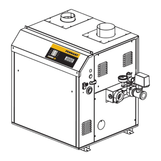
Combustion Air Horizontal Vent Connection Model Connection (Cat III) Vent Pipe Size 20.5 26.5 33.6 *Air and vent connections may be on top or back of the Pennant, and are field convertible. Figure 1a. Dimensional Data - Non Pump Mounted. - Page 6 REAR VIEW Combustion Air Horizontal Vent Connection Model Connection (Cat III) Vent Pipe Size 20.5 26.5 33.6 *Air and vent connections may be on top or back of the Pennant, and are field convertible. Figure 1b. Dimensional Data - Pump Mounted.
-
Page 7: Locating Pump-Mounted Water Heater With Respect To Storage Tank(S)
WARNING with Respect to Storage Tank(s) For indoor installations, as an additional measure For best results, a pump-mounted Pennant water of safety, Laars strongly recommends installation of heater should be located within 15 feet (4.6m) of the suitable Carbon Monoxide detectors in the vicinity of storage tank(s). -
Page 8: Combustion Air From Room
A Pennant appliance may receive combustion air from the space in which it is installed, or it can be *Net Free Area in Square Inches / Square cm ducted directly to the unit from the outside. -
Page 9: Venting
Joint Sealing Permanent duct tape or aluminum tape Pennant units are not allowed to be vented into a common horizontal vent system, unless a properly Table 4. Required Combustion Air Piping Material. -
Page 10: Category Iii Vent
(3.0m) for every additional elbow used. that all appliances attached to the vent be locked out and prevented from operating. Note that the Pennant 2.3 Locating Vent & Combustion Air is equipped with a blocked vent safety (pressure) Terminals switch, as shipped. - Page 11 Pennant 200, 300, 400 Page 11 U.S. Installations (see note 1) Canadian Installations (see note 2) A= Clearance above grade, veranda, porch, 12 inches (30 cm) 12 inches (30 cm) deck, or balcony B= Clearance to window or door that may...
- Page 12 LAARS Heating Systems Page 12 SIGNAGE. Important Note: Massachusetts Code A metal or plastic identification plate shall be Requirement. permanently mounted to the exterior of the building at a minimum height of eight (8) feet From Massachusetts Rules and Regulations 248 above grade directly in line with the exhaust vent CMR 5.08: terminal for the horizontally vented gas fueled...
-
Page 13: Side Wall Combustion Air Terminal
Place in operation the appliance being conditions. inspected. Follow the lighting instructions. If the Pennant is side-wall vented to the same Adjust thermostat so appliance will operate wall, locate the vent terminal at least 3 feet continuously. -
Page 14: Vent Terminals For Outdoor Units
Mettre l'appareil inspecté en marche. Suivre les hangers or floor stands, not by the appliance. instructions d'allumage. Réegler le thermostat de The Pennant’s gas train allows the user to pipe façon continue. the gas from either the right side or the left side of Faire fonctionner le brûleur principal pendant... -
Page 15: Section 4A
Pennant. This sensor may be strapped onto pipe from the inlet supply pressure. The pressure can be 1" to 4" diameter, or inserted into an immersion well. - Page 16 LAARS Heating Systems Page 16 COLD WATER CAUTION: THIS DRAWING SHOWS SUGGESTED MAKE-UP PIPING CONFIGURATION AND VALVING, CHECK WITH LOCAL CODES AND ORDINANCES FOR ADDITIONAL REQUIREMENTS. SYSTEM RETURN SYSTEM SUPPLY SYSTEM PUMP PRIMARY/SECONDARY MANDATORY FOR ALL VARIABLE FLOW SYSTEMS INSTALL AIR VENTS AT HIGH POINTS IN SYSTEM PIPING &...
- Page 17 Pennant 200, 300, 400 Page 17 150°F CAUTION: THIS DRAWING SHOWS SUGGESTED PIPING CONFIGURATION AND VALVING, CHECK WITH LOCAL CODES AND ORDINANCES FOR ADDITIONAL REQUIREMENTS. COLD WATER MAKE-UP 180°F 130°F 180°F SYSTEM PUMP NOTES: PRIMARY/SECONDARY MANDATORY FOR ALL 1. BOILER LOOP IN EXAMPLE IS MAINTAINED AT 180°F.
-
Page 18: Cold Water Make-Up - Boiler
Head loss is for boiler’s heat exchanger only. the system. To ensure a proper operating temperature N/R = not recommended. leading to long boiler life, a flow rate has been Table 8. Water Flow Requirements - PNCH. -
Page 19: Freeze Protection - Boiler
Water Connections — If the Pennant water heater is installed in a closed Pennant Water Heater water supply system, such as one having a backflow preventer in the cold water supply line, the relief valve may discharge periodically, due to thermal expansion. - Page 20 ADDITIONAL REQUIREMENTS. NOTES: 1. OPTIONAL CWMU & RECIRC. LINE LOCATION. 2. LOCATE PENNANT DHW SENSOR OR REMOTE AQUASTAT WELL IN LOWER 1/3 OF TANK. 3. BACK FLOW PREVENTER MAY BE REQUIRED. CHECK LOCAL CODES. 4. THERMAL EXPANSION TANK MAY BE REQUIRED. CHECK LOCAL CODES.
- Page 21 PPM / 17.1 = Grains Per Gallon NOTES: 1. OPTIONAL CWMU & RECIRC. LINE LOCATION. 2. LOCATE PENNANT DHW SENSOR OR REMOTE AQUASTAT WELL IN LOWER 1/3 OF TANK. 3. BACK FLOW PREVENTER MAY BE REQUIRED. CHECK LOCAL CODES. 4. THERMAL EXPANSION TANK MAY BE REQUIRED. CHECK LOCAL CODES.
-
Page 22: Water Flow Requirements - Water Heater
The water are not recommended in areas subject to freezing flow requirements for the Pennant water heater are temperatures, unless proper precautions are taken. based upon the hardness of the water. The water flow... - Page 23 Pennant 200, 300, 400 Page 23 Code Part 1) CSA C22.1, au Canada. N’utilisez AVERTISSEMENT pas les tuyauteries d’eau ou de gaz pour mettre L’appareil doit être relié à la terre conformément à la terre les pièces métalliques de la chaudière;...
- Page 24 LAARS Heating Systems Page 24 120 VAC PUMP (IF EQUIPPED) PUMP TDR 2 TDR 4 PUMP TIME DELAY RLY MAIN POWER SWITCH POWER ON IGNITOR CTRL CTRL BLOWER CTRL 120 VAC CLASS 2 120/24VAC FUSE 50VA TRANSFORMER 24 VAC POWER ON IGNITION BOARD TEMP CONTROL TDR 1...
-
Page 25: Main Power
Temperature Sensor: The sensor supplied loose Recheck all air bleeders as described in Step 4. with the Pennant is installed in the piping or tank, per Check liquid level in expansion tank. With the the suggested piping diagrams. The sensor, Thermistor system full of water and under normal operating 2, is connected to the “9”... -
Page 26: Pennant Control
Loop 1 is the Pennant loop, which uses thermistor sequence, as well. Section 6.5 describes the result of 1, mounted in the inlet of the Pennant. Loop 2 is a air flow faults in more detail. secondary loop, using the auxiliary thermistor (called When the ignition control gets the signal at the thermistor 2) provided loose with the Pennant. -
Page 27: Ignition Control Reaction To Air Flow/Blocked Vent Pressure Switch
°C, program the control as shown in light up to two more times. If successful, the Pennant sections 6.6.6 and 6.6.7. will fire normally. If unsuccessful, the ignition control will lock out. - Page 28 10 s seconds to SP1-td1-St2. If St2=0, stage 2 is energized after the Std time delay. Enables or disables loop 2, so the Pennant control Status of Ch2 on or oFF knows whether or not to recognize that input. 35°F to 240°F...
- Page 29 10 s seconds to SP1-td1-St2. If St2=0, stage 2 is energized after the Std time delay. Enables or disables loop 2, so the Pennant control Status of Ch2 on or oFF knows whether or not to recognize that input. 35°F to 240°F...
-
Page 30: Changing Control Loop 1 Parameters
It can be turned on or off, and the Release the buttons, and CH1 will be displayed. default is on. When it is enabled, the Pennant is called Within 30 seconds, press the upper (or lower) for heat and the auxiliary contacts are energized when button. -
Page 31: Changing The Default Temperature Selection
1, and rt2 is thermistor 2), stop The Pennant will enter the start sequence, as long pushing the buttons. In 30 seconds of button as the unit is being called for heat. The blower... -
Page 32: High Altitude Adjustment And Set Up
Switch off the main electrical disconnect switch. Burner Safety Shutoff Device must be tested. Close all manual gas valves. To test: If freezing is anticipated, drain the Pennant and Close gas shutoff valve with burner be sure to also protect building piping from operating. -
Page 33: Appliance Maintenance And Component Description
7.2.2 Filter The filter used in the Pennant is washable and has 7.2 Appliance Maintenance and an 80% arrestance rating. Since the filter is washable, it will only need replacement occasionally. If filter... -
Page 34: Temperature Control
To reset the switch, unscrew the black cover that 7.2.9 Flow Switch is over the reset button, and push the button. Replace The Pennant uses a paddle-type flow switch to the cover after the switch is reset. ensure that the unit has water flow before ignition is To replace, shut off power to the appliance. -
Page 35: Section 8. Trouble Shooting
Pennant 200, 300, 400 Page 35 Disconnect and remove the wires, conduit and Poor Combustion: Poor combustion should be sensors from all components that are attached to suspected if there is a strong flue gas odor. The the inlet/outlet header. -
Page 36: High Gas Consumption
, first verify that the supply gas pressure is within range temperature signal received 5 to 13 in. w.c. (1.2 to 3.2 kPa). With the Pennant RT1 sensor open or low out-of- running with all stages firing, set the air box pressure to 1.8 in. - Page 37 Pennant 200, 300, 400 Page 37 Item Description Model 200 Model 300 Model 400 COMBUSTION CHAMBER COMPONENTS See Figure 15 Base Assembly 2C1000 3C1000 4C1000 Support, Tile Notch 2C2019 3C2019 4C2019 Chamber, Refractory, Heat Exchanger T2108802 T2108803 T2108804 Assembly, Front Panel, Combustion Chamber...
- Page 38 LAARS Heating Systems Page 38 Item Description Model 200 Model 300 Model 400 JACKET COMPONENTS (continued) See Figure 16 Panel, Lower Access, Jacket 2C3622 2C3622 2C3622 Panel, Filter Side, Upper, Jacket 2C3623 2C3623 2C3623 Panel, Filter Access, Jacket 2C3010 2C3010 2C3010 Weldment, Cover, Air Inlet 2C3700...
- Page 39 Pennant 200, 300, 400 Page 39 Item Description Model 200 Model 300 Model 400 CONTROL PANEL COMPONENTS See Figure 19 Panel, Mounting, Electrical Components 2C7002 3C7002 4C7002 Panel, LED/Control 2C7003 2C7003 2C7003 Bracket, Mounting, Hi-Limt/Pressure Switch 2C7004 2C7004 2C7004 Switch, Pressure, Diaphragm, SPST...
- Page 40 LAARS Heating Systems Page 40 Figure 15. Combustion Chamber Components.
- Page 41 Pennant 200, 300, 400 Page 41 Figure 16. Jacket Components.
- Page 42 LAARS Heating Systems Page 42 Figure 17. Heat Exchanger Components.
- Page 43 Pennant 200, 300, 400 Page 43 ON/OFF 2 STAGE Figure 18. Gas Train Components.
- Page 44 LAARS Heating Systems Page 44 USED ON MODEL 200 ONLY Figure 19. Controls Components. ® 20 Industrial Way, Rochester, NH 03867 • 603.335.6300 • Fax 603.335.3355 1355 Kuehner Drive, Simi Valley, CA 93063 • 800.900.9276 • Fax 800.559.1583 (Sales, Service) Heating Systems Company 480 S.
Need help?
Do you have a question about the PNCH and is the answer not in the manual?
Questions and answers