Table of Contents
Advertisement
Quick Links
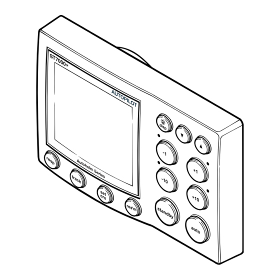
ST7000+ Autopilot Control Head
ST7000+
Autopilot
Control Head
Service Manual
D4403-1
Warning
CE Marking of Equipment/Replacement Parts
If the Raytheon equipment under repair, test, calibration, installation or setting to work carries
the European CE mark, only parts and components supplied or approved for such use by
Raytheon should be used in order to maintain compliance with the relevant CE requirements.
Incorporation, use or attachment, by any means, of parts or components not supplied for or not
approved for such use by Raytheon or, if supplied or approved for use by Raytheon, not properly
fitted in accordance with instructions published, provided or recommended by Raytheon, may
cause the equipment to malfunction and, in particular, to become unsafe or to no longer meet the
relevant CE requirements. In these circumstances, Raytheon Marine Europe Ltd excludes
liability to the fullest extent permissible in law for any loss or damage including any liability for
its contribution to such loss or damage by its negligent acts or omissions .
ST7000+ Autopilot Control Head Service Manual 83141-1 1
Advertisement
Table of Contents

Summary of Contents for Raytheon ST7000+
- Page 1 Incorporation, use or attachment, by any means, of parts or components not supplied for or not approved for such use by Raytheon or, if supplied or approved for use by Raytheon, not properly fitted in accordance with instructions published, provided or recommended by Raytheon, may cause the equipment to malfunction and, in particular, to become unsafe or to no longer meet the relevant CE requirements.
-
Page 2: Chapter 1. Disassembly/Assembly
ST7000+ Autopilot Control Head Chapter 1. Disassembly/Assembly Figure 1: ST7000+ Autopilot Control Head exploded view 2 ST7000+ Autopilot Control Head Service Manual 83141-1... - Page 3 ST7000+ Autopilot Control Head 1.1 ST7000+ Autopilot Control Head spare parts list The item numbers refer to Figure 1: ST7000+ Autopilot Control Head exploded view Item Spare Description Part No. Comments Facia A18001 Keypad set, including A18003 Keypad Display keypad Display kit, including A18004 Display label...
-
Page 4: Chapter 2. Pcb Details
ST7000+ Autopilot Control Head Chapter 2. PCB details 2.1 Input/Output signals (refer to Figure 2. ST7000+ Autopilot Control Head circuit diagram) Wire colour Circuit diagram Description reference P1/P4 +12V nominal DC supply. Yellow P3/P6 SeaTalk data. Intermittent streams of +12V (nominal) pulses. Screen P2/P5 0V supply and signal return. -
Page 5: Circuit Diagram
ST7000+ Autopilot Control Head Circuit diagram Figure 2. ST7000+ Autopilot Control Head circuit diagram ST7000+ Autopilot Control Head Service Manual 83141-1 5... -
Page 6: Pcb Layout
ST7000+ Autopilot Control Head 2.2 PCB Layout Taken from Drawing No: 4332-002 Issue: B Date: 23-07-98 D4501-1 6 ST7000+ Autopilot Control Head Service Manual 83141-1... -
Page 7: Component List
ST7000+ Autopilot Control Head Component List Taken from Drawing No: 4332-002 Issue: B Date: 23-07-98 D4502-1 ST7000+ Autopilot Control Head Service Manual 83141-1 7... - Page 8 ST7000+ Autopilot Control Head Raytheon Marine Company Raytheon Marine Company Recreational Products Recreational Products Anchorage Park 676 Island Pond Road Portsmouth, Hampshire Manchester England PO3 5TD NH 03109-5420, USA Telephone 01705 693611 Telephone 603.647.7530 Fax 01705 694642 Fax 603.634.4756 www.raymarine.com www.raymarine.com...