Table of Contents
Advertisement
WARNING: This appliance is
equipped for (Natural and
Propane) gas. Field conversion is
not permitted other than between
natural or propane gases.
WARNING: IF THE INFORMATION IN THIS MANUAL IS NOT FOLLOWED
EXACTLY, A FIRE MAY RESULT CAUSING PROPERTY DAMAGE, PERSONAL
INJURY, OR LOSS OF LIFE.
–
Do not store or use gasoline or other flammable vapors and liquids in vicinity of this or any
other appliance.
•
Do not try to light any appliance.
•
Do not touch any electrical switch; do not use any phone in your building.
•
Immediately call your gas supplier from a neighbor's phone. Follow the gas
supplier's instructions.
•
If you cannot reach your gas supplier, call the fire department.
– Installation and service must be performed by a qualified installer, service agency,
or the gas supplier.
This is an unvented gas-fired heater. It uses air (oxygen) from the room in which it is
installed. Provisions for adequate combustion and ventilation air must be provided.
Refer to Air For Combustion and Ventilation section on page 7 of this manual.
INSTALLER : DO NOT DISCARD THIS MANUAL - LEAVE FOR HOMEOWNER'S
FUTURE REFERENCE.
This appliance may be installed in an aftermarket, permanently located manufactured
(mobile) home, where not prohibited by local codes. This appliance is for use with the
type of gas indicated on the rating plate only. This appliance is not convertible for use
with other gases.
Questions, problems, missing parts? Before returning to your retailer, call our
customer service department at 1-866-573-0674, 8:00 a.m - 4:30 p.m., EST,
Monday - Friday or e-mail customerservice@usaprocom.com
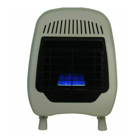
VENT-FREE GAS WALL HEATER BLUE FLAME
MODEL #MD100TBE MD200TBE MD300TBE
CAUTION - FOR YOUR SAFETY
ITEM #0051064 0051118 0051186
Español p. 31
LS-SM-MDTBE-0805
Advertisement
Table of Contents

Subscribe to Our Youtube Channel
Summary of Contents for FeatureComforts MD100TBE
- Page 1 ITEM #0051064 0051118 0051186 VENT-FREE GAS WALL HEATER BLUE FLAME MODEL #MD100TBE MD200TBE MD300TBE Español p. 31 WARNING: This appliance is equipped for (Natural and Propane) gas. Field conversion is not permitted other than between natural or propane gases. CAUTION - FOR YOUR SAFETY...
- Page 2 TABLE OF CONTENTS Important Safety Information......................3 Product Features..........................5 Air For Combustion and Ventilation....................7 Installation ............................10 Operation............................18 Care & Maintenance........................22 Troubleshooting..........................23 Replacement Parts........................26 WARNING: READ THE INSTALLATION & OPERATION INSTRUCTIONS BEFORE USING THIS APPLIANCE. IMPORTANT: Read instructions and warnings carefully before starting installation. Failure to follow these instructions may result in a possible fire hazard and will void the warranty.
- Page 3 IMPORTANT SAFETY INFORMATION IMPORTANT: Read this owner’s manual carefully and completely before trying to assemble, operate, or service this heater. Improper use of this heater can cause serious injury or death from burns, fire, explosion, electrical shock, and carbon monoxide poisoning. Only a qualified installer, service agent, or local gas supplier may install and service this product.
- Page 4 Do not place Propane/LP supply tank(s) inside any structure. Place Propane/LP supply tank(s) outdoors. Do not install item #0051064 (Model #MD100TBE) in a bathroom. Do not install Item #0051118 (Model #MD200TBE) and Item #0051186 (Model #MD300TBE) in a bedroom or bathroom.
- Page 5 PRODUCT FEATURES SAFETY PILOT This heater has a pilot with an Oxygen Depletion Sensing (ODS) safety shutoff system. The ODS/pilot shuts off the heater if there is not enough fresh air. PIEZO IGNITION SYSTEM This heater is equipped with an electronic piezo control system. This system requires AAA batteries (provided).
- Page 6 PREPARING FOR INSTALLATION Before beginning assembly or operation of the product, make sure all parts are present. Compare parts with package contents list. If any part is missing or damaged, do not at- tempt to assemble, install, or operate the product. Contact customer service for replacement parts.
- Page 7 AIR FOR COMBUSTION AND VENTILATION WARNING: This heater should not be installed in a confined space or unusually tight construction unless provisions are provided for adequate combustion and ventilation air. Read the following instructions to ensure proper fresh air for this and other fuel burning appliances in your home.
- Page 8 DETERMINING FRESH-AIR FLOW FOR HEATER LOCATION Determining if You Have a Confined or Unconfined Space Use this worksheet to determine if you have a confined or unconfined space. Space: Includes the room in which you will install heater plus any adjoining rooms with doorless passageways or ventilation grills between the rooms.
- Page 9 WARNING: If the area in which the heater may be operated is smaller than that defined as an unconfined space or if the building is of unusually tight construction, provide adequate combustion and ventilation air by one of the methods described in the National Fuel Gas Code, ANS Z223.1, Section 5.3 or applicable local codes.
- Page 10 WARNING: A qualified technician must install heater. Follow all local codes. WARNING: Never install the heater: • in a bathroom - Item # 0051064 (Model # MD100TBE) • in a bedroom or bathroom - Item # 0051118 (Model # MD200TBE) and Item # 0051186 (Model # MD300TBE) •...
- Page 11 LOCATING HEATER This heater is designed to be mounted on a wall. Fig. 4 - Moving Thermostat Sensing Bulb For convenience and efficiency, install heater: 1) Where there is easy access for operation, inspection, and service. 2) In the coldest part of room. INSTALLING THERMOSTAT SENSING BULB 1.
- Page 12 1. Tape mounting bracket to wall where heater Clearances (inches) will be located. Make sure mounting bracket is level. Item # 0051064 (Model # MD100TBE) WARNING: Maintain minimum clearances shown in Fig. 3. If you can, provide greater 8 3/4 in. 12 3/16 in.
- Page 13 Attaching to Wall Anchor Method Fig. 7 - Folding Anchor For attaching mounting bracket to hollow walls (wall areas between studs) or solid walls (concrete or masonry): 1. Drill holes at marked locations using 5/16-inch drill bit. For solid walls (concrete or masonry), drill at least 1 inch deep.
- Page 14 CONNECTING TO GAS SUPPLY WARNING: A qualified service technician must connect heater to gas supply. Follow all local codes. WARNING: This appliance requires a 3/8-inch NPT (National Pipe Thread) inlet connection to the pressure regulator. WARNING: Never connect heater to private (non-utility) gas wells. This gas is commonly known as wellhead gas.
- Page 15 Fig. 11 - Gas Connection 3/8 in NPT Pipe Nipple Ground Joint Tee Joint Union Reducer Test Equipment Bushing to Gauge Shutoff 1/8 in NPT Connection * Valve 1/8 in NPT Inlet Pipe From Gas Plug Tap Meter (11 in W. C. to 14 in W.
- Page 16 CONNECTING TO GAS SUPPLY (CONTINUED) CAUTION: DO NOT install two gas lines at the same time. DO NOT open the cover while the heater is running. Heater is pre-set at factory for propane gas; no changes are required for connecting to propane. Only a qualified installer or service technician can perform gas selection and connecting to gas supply.
- Page 17 CHECKING GAS CONNECTIONS WARNING: Test all gas piping and connections for leaks after installing or servicing. Correct all leaks immediately. WARNING: Never use an open flame to check for a leak. Apply a mixture of liquid soap and water to all joints. If bubbles form, there may be a leak. Correct all leaks immediately. Pressure Testing Gas Supply Piping System Test Pressures In Excess Of 1/2 PSIG ( 3.5kPa ) 1.
- Page 18 OPERATION FOR YOUR SAFETY READ BEFORE LIGHTING WARNING: If you do not follow these instructions exactly, a fire or explosion may result causing property damage, personal injury, or loss of life. NOTICE: During initial operation of new heater, burning logs will give off a paper burning smell.
- Page 19 LIGHTING INSTRUCTIONS Unscrew ignitor cap and install a AAA battery with the + pointing out. Replace cap. 1. STOP! Read the safety information on the side of the heater. 2. Make sure equipment shutoff valve is fully open. 3. Turn control knob clockwise to the OFF position.
- Page 20 Fig. 19 - Control Knob Position Ignitor Button Control knob THERMOSTAT CONTROL OPERATION The thermostatic control used on this model differs from standard thermostats. Standard ther- mostats simply turn the burner on and off. The thermostat used on this heater senses the room temperature.
- Page 21 INSPECTING BURNERS Check pilot flame pattern and burner flame patterns often. PILOT FLAME PATTERN Figure 20 shows a correct pilot flame pattern. Figure 21 shows a incorrect pilot flame pattern. The incorrect pilot flame is not touching the thermocouple. This will cause the thermocouple to cool, which shuts the heater off.
- Page 22 CARE AND MAINTENANCE WARNING: Turn off heater and let cool before servicing CAUTION: You must keep control areas, burner, and circulating air passageways of heater clean. Inspect these areas of heater before each use. Have heater inspected yearly by a qualified service technician.
- Page 23 TROUBLESHOOTING WARNING: If you smell gas: • Shut off gas supply. • Do not try to light any appliance. • Do not touch any electrical switch; do not use any phone in your building. • Immediately call your gas supplier from a neighbor’s phone. Follow the gas supplier’s instructions.
- Page 24 Problem Possible Cause Corrective Action ODS/pilot lights but flame 1. Control knob is not fully 1. Press in control knob goes out when control knob pressed in. fully. is released. 2. Control knob is not pressed 2. After ODS/pilot lights, in long enough.
- Page 25 Problem Possible Cause Corrective Action Slight smoke or odor during 1. Residues from 1. Problem will stop after a few initial operation manufacturing process. hours of operation. Heater produces a whistling 1. Turning control knob to 1. Turn control knob to low (1) noise when burner is lit.
- Page 26 REPLACEMENT PARTS NOTE: Use only original replacement parts. This will protect your warranty coverage for parts replaced under warranty. PARTS UNDER WARRANTY Contact authorized dealers of this product. If they can’t supply original replacement parts, call Customer Service toll free at 1-866-573-0674 for referral information. When calling Customer Service or your dealer, have ready: •...
- Page 27 PARTS LIST(Item # 0051064 Model # MD100TBE) For replacement parts, call our customer service department at 1-866-573-0674, 8:00 a.m - 4:30 p.m., EST, Monday - Friday or e-mail customerservice@usaprocom.com Part. Description Part # Front Panel Assembly MEB2100 ODS Pilot Assembly...
- Page 28 PARTS LIST(Item # 0051118 Model # MD200TBE) For replacement parts, call our customer service department at 1-866-573-0674, 8:00 a.m - 4:30 p.m., EST, Monday - Friday or e-mail customerservice@usaprocom.com Part. Description Part # Front Panel Assembly MEB3100 ODS Pilot Assembly NDD0308X800-MEDⅡ...
- Page 29 PARTS LIST(Item # 0051186 Model # MD300TBE) For replacement parts, call our customer service department at 1-866-573-0674, 8:00 a.m - 4:30 p.m., EST, Monday - Friday or e-mail customerservice@usaprocom.com Part. Description Part # Front Panel Assembly MEB5100 ODS Pilot Assembly NDD0308X800-MEDⅡ...
- Page 30 2-YEAR LIMITED WARRANTY The manufacturer warrants this product to be free from defects in workmanship and material present at time of shipment from the factory for two (2) years from the date of purchase. This warranty applies only to the original purchaser. The manufacturer agrees to correct such defect at no charge or, at our option, replace the product with a comparable or superior model.
Need help?
Do you have a question about the MD100TBE and is the answer not in the manual?
Questions and answers