
Summary of Contents for FSN MDVR IPS700A
- Page 1 MDVR IPS700A Medical Digital Video Recorder Installer User’s Guide Before connecting, operating or adjusting this product, please read this instruction booklet carefully and completely.
-
Page 2: Table Of Contents
Table of Contents Introduction ....... . . 3 Symbol Definitions ......4 Safety Instructions . -
Page 3: Introduction
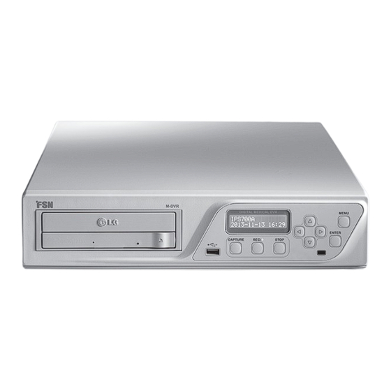
Overview MDVR, part number IPS700A, is a medical digital video recorder from FSN Medical Technologies. It is intended to record and store video and still image from operating devices for later playback or transfer to other media. MDVR is an advanced high quality video processing system that has built-in capabilities for signal source selection, multiple resolutions, and control through RS232C, TCP/IP or Android app. -
Page 4: Symbol Definitions
Symbol Definitions The following symbols appear on the product, its labeling, or the product packing. Each symbol carries a special definition, as defined below: AC Voltage Switches on power Switches off power Contained spare fuse Consult accompanying docu- Dangerous : High Voltage ments Indicates protective earth Power adapter... -
Page 5: Safety Instructions
Safety and Instructions Please read the following safety instructions as they are designed to prevent damage to property and harm to the user. Warning / Caution Failure to follow directions noted by this symbol could result in bodily harm or dam- age to equipment. -
Page 6: Caution
Caution CAUTION RISK OF ELECTRICAL SHOCK DO NOT OPEN This symbol alerts the user that important literature concerning the operation of this unit has been included. Therefore, it should be read carefully in order to avoid potential problems. This symbol warns the user that un-insulated voltage within the unit may have sufficient magnitude to cause electrical shock. - Page 7 If the power source is a 240 V AC supply, use the tandem (T blade) type attachment plug with ground conductor power cord that meets the respective European country’s safety regulations. The hospital-grade plug for medical products intended for use in Denmark has DEMKO approval and is rated 13 amps at 250Vac.
-
Page 8: Parts
Recycling : Follow local governing ordinances and recycling plans regarding the recycling or disposal of this equipment. Servicing Do not attempt to service the system yourself as opening or removing covers may expose you to dangerous voltages or other hazards, and will void the warranty. Refer all servicing to quali- fied service personnel. -
Page 9: Package Contents
Package Contents Item Description Pack Qty MDVR (IPS700A) unit ........1 User Guide . -
Page 10: Ips700A Sample System Configuration
MDVR Sample System Configuration Saved to Media: • CD Display Monitor • DVD Playback • Blu-ray • USB • FTP Server Medical Digital Video Recorder Start and stop Control with foot pedal Interface or hand switch. Source Signals • VGA •... -
Page 11: Connectors
Connectors Blu-ray Disk Network port RS232C Capture button DVI-D out Record button VGA out Stop button DVI-D in Direction button VGA in Enter button CVBS in Menu button CVBS out Earth Terminal S-Video in AC ON/OFF SWITCH Audio in/out AC in Foot pedal recording/capture English - 11 FSN1949 - 4/2014... -
Page 12: Connect Input Video Sources
Connect Input Signals MDVR has connections to receive signals as DVI-D, VGA, CVBS, and S-Video. Specific applications will determine the type of input signal sources that will be connected to MDVR. Never use this system with damaged cords. Keep all cords away from areas where they may cause tripping. MDVR back panel Connect input video signals here. -
Page 13: Connect Power
Connect Power Only use the specified plug and voltage. Power requirements are: AC 100~240V / 50~60Hz , 2A(max). Improper power may cause electric shock or Use the supplied 6 ft. hospital grade AC power cord. equipment damage. To avoid the risk of electric shock, this equipment must only be connected to a power supply with protective grounding. -
Page 14: Connect A Remote Control Device
Connect A Remote Control Device The preferred way to record images and video with MDVR is by connecting a remote control device, such as a touch screen tablet. For specific instructions, please refer to the user guide that accompanies the remote control device that will be connected to MDVR. Example: Touch screen tablet connection using a wireless router. -
Page 15: Methods Of Operation
Methods of Operation Most features in the MDVR unit are intuitively handled by a remote control device, such as a touch screen tablet and interface software. Capture and record functions are designed for easy end user operation via the tablet interface. There are a few configuration settings that can only be accessed through MDVR’s front keypad and LCD. -
Page 16: Front Panel Control Keypad (Osd)
Front Panel Control Keypad (OSD) The preferred method of altering most features in the MDVR system is the remote control device, which is usually a tablet. A secondary method for altering most features is maneuvering through the menus on the small front panel LCD screen by using the control keypad. Below are funtions and settings that are available through the MDVR front panel LCD and key- pad. - Page 17 Front Panel Control Keypad (OSD) Menu Configuration Screens Press MENU to enter configure mode, then press the top 1. Input Source arrow to cycle through the list of adjustments. Use the arrow keys and the ENTER key to configure each setting as described below.
-
Page 18: General Specification
General Specification Item Description Unit Model IPS7000A (Signal processor for Medical) Input DVI‐D ,VGA, CVBS, S‐VIDEO Port Output DVI‐D, VGA, CVBS Port Control key 9 button (CAPTURE, REC, STOP, SELECT, UP, DOWN, PLUS, MINUS, MENU) OSD language English Power AC 100~240V / 50~60Hz , 2A(max) Serial communication RS-232C, 115200 baud Rx Network... - Page 19 Input/Output Connector Specification Pin No. Assignment Pin No. Assignment No Connection Green Ground-Sync Blue Ground Ground DDC Data DDC 5V Standby H.Sync Ground-Red V.Sync Ground-Green DDC Clock Ground-Blue Pin No. Assignment Pin No. Assignment T.M.D.S. Data2 No Connection T.M.D.S. Data2+ +5V Power T.M.D.S.
- Page 20 Input/Output Timing DVI, VGA input timing Horizontal Frequen- Vertical Frequency Resolution Pixel clock (MHz) cy (KHz) (Hz) 640 x 350 @70Hz 31.469 70.087 25.175 640 x 400 @60Hz 31.469 59.941 25.175 640 x 480 @60Hz 31.469 59.940 25.175 640 x 480 @75Hz 37.500 75.000 31.500...
-
Page 21: Recording Time
Power Consumption Mode Consumption (W) State Record BLURAY data backup Record HDD recording Normal Standby Power off Recording Time Record/Backup Hours Size Resolution Source Device 22 Gbyte 1080p Internal disk 12 Gbyte 720p 2 Gbyte 480p 25 Gbyte 1080p Blu-ray 25 Gbyte 720p Surgical camera... -
Page 22: Mechanical Drawing
Mechanical Drawing 355 mm / 13.98 in. 22 - English FSN1949 - 4/2014... -
Page 23: Troubleshooting
Troubleshooting Problem Possible Solution No power Check fuse in AC Inlet. If fuse has failed, replaced with similarly rated new part. Will not record Verify that there is sufficient space available on the internal disk. No response from MDVR Re-boot the system. Disc or USB failure Make sure that the media being used is not write protected. -
Page 24: Contacts
Foreseeson Custom Displays, Inc. Foreseeson GmbH 2210 E. Winston Road Industriestrasse 38a Anaheim, CA 92806 USA 63150 Heusenstamm, Germany Tel: 714-300-0540 Tel: +49 6104 64398 0 Fax: 714-300-0546 Fax: +49 6104 64398 11 Foreseeson Korea Foreseeson UK Ltd. 404B, Pangyoinnovalley B Unit 2 Kingsmill Business Park 253 Pangyo-ro Chapel Mill Road...
Need help?
Do you have a question about the MDVR IPS700A and is the answer not in the manual?
Questions and answers