Table of Contents
Advertisement
Quick Links
Main Components:
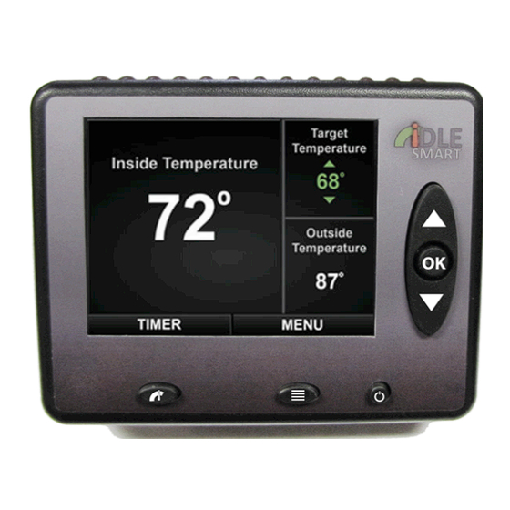
Idle Smart Display Unit
Idle Smart Base Unit
Idle Smart ProSmart Harness™
CanBus Connector and Cable
Temperature Sensors (2)
Outside Temperature Extension Cable
Safety Switches:
Park Brake Safety Switch
Neutral Safety Switch
Hood Safety Switch
Display Mounting:
Black Ethernet Cord (Base Unit to Display Unit connection)
Display Unit Mounting Plate (RJ45 Connector & screws)
Coil cord
Guides:
Quickstart Guide
User Manual
Installation Guide
Misc. Components:
Sealed Crimp Connectors (10)
UV Resistant Zip Ties
Alcohol swabs
Epoxy Putty
Warning Stickers (4)
"Equipped With Idle Smart" door magnet
Envelope with Important Vehicle Owner Information
Note: An ASE qualified mechanic is required for the safe and accurate installation of Idle Smart given the knowledge
needed of the associated components referenced in this document. Many vehicles have differing locations for some
of the required integration points in this installation process. Be sure all wiring is secured to the truck's frame so as
not to interfere with moving parts. Vehicle for installation must conform to SAE J1939 CanBus specification for
communication as required for proper Idle Smart operation.
Idle Smart Installation Guide
Version 1.5 – March 2014
Installation Guide
Idle Smart Display Unit
Idle Smart Base Unit
Page 1
Advertisement
Table of Contents

Summary of Contents for Idle Smart Display Unit
- Page 1 Envelope with Important Vehicle Owner Information Note: An ASE qualified mechanic is required for the safe and accurate installation of Idle Smart given the knowledge needed of the associated components referenced in this document. Many vehicles have differing locations for some of the required integration points in this installation process.
- Page 2 □ Step 2: Verify CanBus Information Verify that the truck has J1939 protocol installed, which is required for Idle Smart to work. To verify that the truck will work with Idle Smart, pins must be included in C and D on the 9-pin connector.
- Page 3 The Idle Smart standard installation is to increase the idle RPMs by connecting to the cruise control documented below. Idle Smart will be installed to either the cruise control or to the PTO but never to both. Some applications require Idle Smart to connect to the PTO. In this case, Idle Smart will provide notification for PTO installations.
- Page 4 Idle Smart will now start the truck and the timer should start to count down to 0:00. After the truck has started and the timer hits 5:00, Idle Smart should increase the RPMs.
- Page 5 The Installation is now complete and ready for use. Please instruct the vehicle user to refer to the Idle Smart Quick Start Guide and User Manual for product familiarity before use. Idle S mart I nstallation G uide ...
Need help?
Do you have a question about the Display Unit and is the answer not in the manual?
Questions and answers