
Summary of Contents for RBH Sound Axiom V
- Page 1 Integrated Access Control and Security Management System HARDWARE MANUAL new generation building security...
- Page 2 RBH Access Technologies Inc., Brampton, Ontario, Canada. Trademark ™ AxiomV is the trademark of RBH Access Technologies Inc. Windows is a trademark of Microsoft Corporation. All other product names mentioned herein are the property of their respective owners. Use of a term in this book should not be regarded as affecting the validity of any trademark or service mark.
-
Page 3: Table Of Contents
C o n t e n t s ™ CHAPTER 1 INTRODUCING AXIOMV ..............1 CHAPTER 2 NETWORK CONTROLLER (NC-100) ..........4 ..........................5 ONNECTION ETAILS Power..............................5 Host Interface ............................5 C-NET CH1 and CH2 ..........................6 D-NET CH1 and CH2 ..........................6 Auxiliary Output ............................. - Page 4 ONNECTION ETAILS Auxiliary Power Output ........................39 Backup Battery (Red and Black Lead) ....................39 AC Power ............................. 39 Powering From DC ..........................39 Fire Release Input (Terminals) ......................39 Tamper..............................39 ™ AxiomV Hardware Guide RBH Access Technologies Inc.
- Page 5 PC To Controller ..........................58 C-NET: (NC-100 to NC-100)........................ 58 D-NET: (NC-100 to RC-2, IOC-16) ..................... 58 RC-2 to Reader: ............................ 58 Input / Output Port Circuit Loop:......................58 INDEX ..........................59 ™ RBH Access Technologies Inc. AxiomV Hardware Guide...
-
Page 7: Chapter 1 Introducing Axiomv
System combines access control, building management, and ™ security monitoring in a highly integrated and expandable package. AxiomV Security Management Software runs on a standard IBM compatible PC and is designed for use in installations ranging from simple two door systems to complex systems covering multiple sites and containing thousands of access points and tens of thousands of cardholders. - Page 8 Seven input configurations are provided ranging from simple normally closed contacts to two EOL loops for high security applications. ™ The system architecture utilized by AxiomV is extremely powerful, flexible, and expandable. As new devices are developed for the system, compatibility will be maintained with existing network devices, ensuring continued possibilities for system upgrading and expansion.
- Page 9 Chapter 1 ™ Introducing AxiomV ™ AxiomV System Diagram ™ RBH Access Technologies Inc. AxiomV Hardware Guide...
-
Page 10: Chapter 2 Network Controller (Nc-100)
N e t w o r k C o n t r o l l e r ( N C - 1 0 0 ) ™ The AxiomV access control system consists of one or more network controllers (NC-100). All information required by the controller is downloaded from the PC and stored locally in battery backed flash memory. -
Page 11: Connection Details
The NC-100 requires 9-14vdc and draws about 220mA in the standard 256k RAM configuration. Host Interface The Host interface connects the NC-100 to a PC through either an RS232, TCP/IP Ethernet or an RS485 (4 wire) interface. ™ RBH Access Technologies Inc. AxiomV Hardware Guide... -
Page 12: C-Net Ch1 And Ch2
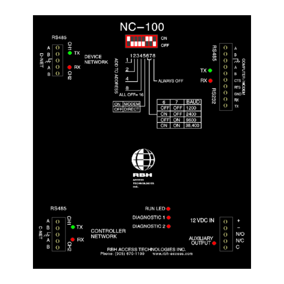
Note: To Reset Panel – All DIP switches must be off. DIP Switch DIP Switch Function 1 - 4 Controller Address Direct Host Connection Controller Baud Rate 4 Wire RS485 (Always Off) ™ AxiomV Hardware Guide RBH Access Technologies Inc. -
Page 13: Controller Addressing
Direct Connect Leave DIP switch 5 off, modem selection is no longer supported. Direct Connect / Modem Selection DIP Switch 5 Interface Type Direct Connect To PC Modem ™ RBH Access Technologies Inc. AxiomV Hardware Guide... -
Page 14: Computer Port Baud Rate Selection (Master Only)
The master controller is connected to a serial port on the PC. The PC serial port is assigned to the C-NET under the Communication Port Setup screen in the ™ AxiomV software. Normally the baud rate is set to 9600 for direct connection to the PC using the standard RS232 interface. -
Page 15: Rs232 Connection
PC to NC-100 - RS232 Interface Wiring Cable Specification 3 or 4 conductor shielded, 18 to 22 AWG Maximum Cable Length 9600 baud 150 feet (45meters) 38400 baud 30 feet (9 meters) ™ RBH Access Technologies Inc. AxiomV Hardware Guide... -
Page 16: Rs485 Connection
A/B connections at the PC end. PC to NC-100 Connection – 4 Wire RS485 Interface Wiring Cable Specification 2 twisted pair, individually shielded, 18 to 22 AWG Maximum Cable Length 4000 feet (1200 meters) ™ AxiomV Hardware Guide RBH Access Technologies Inc. -
Page 17: C-Net (Controller Network)
Channel 1 on its downstream neighbor. Channel 2 on the last controller is wired back to Channel 1 on the master controller to complete the network ring as per the following diagram. ™ RBH Access Technologies Inc. AxiomV Hardware Guide... - Page 18 Chapter 2 NC-100 C-NET (Controller Network) Connection Diagram ™ AxiomV Hardware Guide RBH Access Technologies Inc.
-
Page 19: C-Net Cable
Diagnostic LEDs 1 and 2 These LEDs are used for factory diagnostics only. 1 – Flashes when receiving a message from other controller. 2 – Flashes in normal mode (sending messages to other controllers). ™ RBH Access Technologies Inc. AxiomV Hardware Guide... -
Page 20: D-Net Device Network
Connect RC-2 Controllers (up to four) first in the D-NET, followed by up to sixteen IOC-16 Controllers as per the diagram on page 18. ™ AxiomV Hardware Guide RBH Access Technologies Inc. - Page 21 Chapter 2 NC-100 Device Controller Address Assignment Address Device Controller 1 – 4 RC-2 5 – 20 IOC-16 D-NET (Device Network) Connection Diagram ™ RBH Access Technologies Inc. AxiomV Hardware Guide...
-
Page 22: D-Net Maximum Cable Length
Because the UNC does not have termination jumpers, the first device connected to the UNC500 will have termination as will the last device on that DNET. ™ AxiomV Hardware Guide RBH Access Technologies Inc. -
Page 23: Clearing Nc-100 Memory
6. Reapply power to the controller. Clearing the RAM in this manner is only necessary in the rare occasion where RAM is completely corrupted and the system is unable to communicate with the ™ RBH Access Technologies Inc. AxiomV Hardware Guide... -
Page 24: Chapter 3 Reader Controller (Rc-2)
AC power, battery voltage, reader, and auxiliary fuses are all monitored. Status LEDs indicate the status of all inputs and outputs, AC fault, low voltage, fuse blown, communication activity, and run information. ™ AxiomV Hardware Guide RBH Access Technologies Inc. - Page 25 Chapter 3 RC-2 RC-2 (Reader Controller) Silkscreen Legend ™ RBH Access Technologies Inc. AxiomV Hardware Guide...
-
Page 26: Connection Details
12 to 18vac and can deliver up to 3Amps. Use a 40VA transformer if the lock draws 2Amps or less. Use an 80 VA transformer if the current draw is between 2Amps and 3Amps. ™ AxiomV Hardware Guide RBH Access Technologies Inc. -
Page 27: Main Ac Power (Terminals 27, 28 Side B)
The fire release function works best when all reader input and output configurations are set to default (check Chapter 9 in the ™ AxiomV User Manual for default settings). Fire release functions should be thoroughly tested following any change to RC-2 inputs and outputs. -
Page 28: Dip Switch Settings
The AC high LED comes on when the AC voltage is above 20volts RMS. AC Low The AC low LED comes on when the AC voltage drops below 14volts RMS. Battery Trouble The battery trouble LED indicates that the battery voltage is below 11volts. ™ AxiomV Hardware Guide RBH Access Technologies Inc. -
Page 29: Reader Fuse
PC. The frequency and ™ duration of the test are programmable from the AxiomV software. Typically the battery is tested once every day and the test duration is thirty seconds. -
Page 30: Inputs
This input can be used as a general-purpose input if the door contact is not ™ required. If not used, leave the default RTE settings in the AxiomV software configuration. -
Page 31: Input Circuit Types
Loop Resistance State Short Restore Open Circuit Alarm Normally Open, No Resistor Loop Resistance State Short Alarm Open Circuit Restore Normally Closed, One Resistor Loop Resistance State Short Trouble Restore Open Circuit Alarm ™ RBH Access Technologies Inc. AxiomV Hardware Guide... - Page 32 This circuit provides a high degree of supervision and detects both short and open circuit fault conditions. Use this circuit in high security applications. Normally Open, One Resistor Loop Resistance State Short Alarm Restore Open Circuit Trouble ™ AxiomV Hardware Guide RBH Access Technologies Inc.
- Page 33 Normally Open And Normally Closed, One Resistor Loop Resistance State Short Alarm Restore Open Circuit Alarm This circuit type is used where normally open and normally closed contacts are used in the same loop. ™ RBH Access Technologies Inc. AxiomV Hardware Guide...
-
Page 34: Outputs
Outputs can be programmed to operate in a default mode described below or they can be used as general-purpose outputs. However, ™ the output definition in the AxiomV configuration software should never be left blank. If the output is unused, use the default output definitions provided in ™... -
Page 35: Default Output Operation
For magnetic locks, the relay should be configured from the PC as normally energized for fail-safe operation. If power fails (AC and battery) or the fire input is released, the power to the magnetic lock is removed and the door is opened. ™ RBH Access Technologies Inc. AxiomV Hardware Guide... -
Page 36: Forced / Tamper (Relay Outputs 2A, 2B)
Forced / Tamper (Relay Outputs 2A, 2B) Output 2 turns on if the door is forced open or if a reader tamper is detected. This output remains on for as long as the alarm condition exists. ™ AxiomV Hardware Guide RBH Access Technologies Inc. -
Page 37: Door Held Open (Electronic Outputs 3A, 3B)
Output 3 turns on if the door is held open longer than the PC programmed limit. This output remains on until the door closes. During the warning period, this output will pulse every second. Door Held Open Alarm Output Connection Diagram ™ RBH Access Technologies Inc. AxiomV Hardware Guide... -
Page 38: Alarm Shunt (Electronic Outputs 4A, 4B)
Normally the shunt output is used to shunt the door contact if a secondary alarm panel monitors the contact. Alarm Shunt Output Connection Diagram ™ AxiomV Hardware Guide RBH Access Technologies Inc. -
Page 39: Access Point Operating Modes
The Buzzer emits one long beep and the green LED turns on for the duration of the unlock time. Access Denied The Buzzer emits two short beeps and the red LED flashes twice. ™ RBH Access Technologies Inc. AxiomV Hardware Guide... -
Page 40: Reader Connection Diagrams
5-conductor, stranded, shielded cable (not twisted), 20 to 22 AWG Maximum Cable Length 22 AWG Cable: 250 feet (75 meters) 20 AWG Cable: 500 feet (150 meters) Reader wire colours may vary for different reader manufactures. Please verify your wiring. ™ AxiomV Hardware Guide RBH Access Technologies Inc. -
Page 41: Cable Specification
7-conductor, stranded, shielded cable (not twisted), 20 to 22 AWG Maximum Cable Length 22 AWG Cable: 250 feet (75 meters) 20 AWG Cable: 500 feet (150 meters) Reader wire colours may vary for different reader manufactures. Please verify your wiring. ™ RBH Access Technologies Inc. AxiomV Hardware Guide... -
Page 42: Cable Specification
6-conductor, stranded, shielded cable (not twisted), 20 to 22 AWG Maximum Cable Length 22 AWG Cable: 250 feet (75 meters) 20 AWG Cable: 500 feet (150 meters) Reader wire colours may vary for different reader manufactures. Please verify your wiring. ™ AxiomV Hardware Guide RBH Access Technologies Inc. -
Page 43: Cable Specification
7-conductor, stranded, shielded cable (not twisted), 20 to 22 AWG Maximum Cable Length 22 AWG Cable: 250 feet (75 meters) 20 AWG Cable: 500 feet (150 meters) Keypad wire colours may vary for different keypad manufactures. Please verify your wiring. ™ RBH Access Technologies Inc. AxiomV Hardware Guide... -
Page 44: Chapter 4 Input/Output Controller (Ioc-16)
If the I/O point is configured as and output, the LED is off if the output is de-energized and on if the output is energized. IOC-16 (I/O Controller) Silkscreen Legend ™ AxiomV Hardware Guide RBH Access Technologies Inc. -
Page 45: Connection Details
Fire release functions should be thoroughly tested following any change to IOC-16 outputs. ******************************************************************************** Tamper Connect the tamper leads to a normally closed cabinet tamper switch. If a cabinet tamper switch is not used, the tamper leads should be shorted. ™ RBH Access Technologies Inc. AxiomV Hardware Guide... -
Page 46: Dip Switch 1 Settings
RC-2s). Addresses must be unique and the network will not operate properly if duplicate addresses are programmed. IOC-16 Addressing Switch 1 Switch 2 Switch 3 Switch 4 Switch 5 Address ™ AxiomV Hardware Guide RBH Access Technologies Inc. -
Page 47: Status Led's
The backup battery is protected from deep discharge and possible irreversible damage during a prolonged ac power failure. The battery voltage is continuously monitored and disconnected if the voltage drops below 10volts. ™ RBH Access Technologies Inc. AxiomV Hardware Guide... -
Page 48: Input / Output Selection
8 are programmed with DIP switches 1A and 2A, and ports 9 to 16 are programmed with DIP switches 1B and 2B. Ports 1 – 8 Input/ Output Selection Switches 1A, 2A Input Output Ports 9 – 16 Input/ Output Selection Switches 1B, 2B Input Output ™ AxiomV Hardware Guide RBH Access Technologies Inc. -
Page 49: Inputs
Normally energized outputs are used for fail-safe operation where it is essential that the output return to a safe state when the system fails due to power loss, communications failure, or fire. IOC-16 Output Connection Diagram ™ RBH Access Technologies Inc. AxiomV Hardware Guide... -
Page 50: Switching Inductive Devices (Locks, Bells)
Elevator Control ™ AxiomV provides extensive elevator access control capability. A standard reader or keypad is mounted in the elevator cabin(s). Upon presentation of a valid code by a user, the system enables all floors that the user is authorized to access. - Page 51 Chapter 4 IOC-16 Elevator Control Overview ™ RBH Access Technologies Inc. AxiomV Hardware Guide...
- Page 52 Chapter 4 IOC-16 Elevator Control Connection Diagram Note: Configure all outputs on the IOC-16 as normally energized. ™ AxiomV Hardware Guide RBH Access Technologies Inc.
-
Page 53: Chapter 5 Nrc2000 & Nurc2000
Chapter 4 IOC-16 C h a p t e r 5 N R C 2 0 0 0 & N U R C 2 0 0 0 ™ RBH Access Technologies Inc. AxiomV Hardware Guide... -
Page 54: Wiring
The NRC2000 uses an IRC2000 board to provide most of the functionality of the RC2 board to the Axiom system. The NRC2000 firmware version 3 is based on RC firmware version 34, and includes all updates and bug fixes associated with that version. ™ AxiomV Hardware Guide RBH Access Technologies Inc. -
Page 55: Modification
4) Dual RS485 redundant communications – has only a single channel so must be wired differently! Technical bulletin TB53 will show how to modify the IRC2000 board and how to connect to the power supply to monitor for ‘Battery Low’ and ‘AC Failure’. ™ RBH Access Technologies Inc. AxiomV Hardware Guide... -
Page 56: Chapter 6 Pc-100
Communication Channel LEDs – Each communication channel has a green transmit LED and a red receive LED. Normally flashing at a rate of once a second, DIAG2 will flash twice as fast if the unit is offline with the Axiom Device network. ™ AxiomV Hardware Guide RBH Access Technologies Inc. - Page 57 S p e c i f i c a t i o n s ™ RBH Access Technologies Inc. AxiomV Hardware Guide...
-
Page 58: Nc-100 Specification
Housing dimensions: H 9.75in x W 6.875in x D 3.25in (25 x 18 x 10 cm) Operating temperature: 0 to 70C (35 - 150 Operating Humidity: 20 to 80% RH (non-condensing) ™ AxiomV Hardware Guide RBH Access Technologies Inc. -
Page 59: Specification
Housing dimensions: H 9.75in x W 6.875in x D 3.25in (25 x 18 x 10 cm) Operating temperature: 0 to 70C (35 - 150 Operating Humidity: 20 to 80% RH (non-condensing) ™ RBH Access Technologies Inc. AxiomV Hardware Guide... -
Page 60: Ioc-16 Specification
Housing dimensions: H 9.75in x W 6.875in x D 3.25in (25 x 18 x 10 cm) Operating temperature: 0 to 70C (35 - 150 Operating Humidity: 20 to 80% RH (non-condensing) ™ AxiomV Hardware Guide RBH Access Technologies Inc. -
Page 61: Nrc-2000 Specification
Real Time Clock: Dallas DS1994 with battery back up Housing dimensions: H 12in. x W 14in. x D 3½in. Operating temperature: 0 to 70C (35 - 150F) Operating Humidity: 20 to 80% RH (non-condensing) ™ RBH Access Technologies Inc. AxiomV Hardware Guide... -
Page 62: Nurc-2000 Specification
9600, 28800, 38400, or 56000 Real Time Clock: Dallas DS1994 with battery back up Board dimensions: H 3in. x W 6½in. Operating temperature: 0 to 70C (35 - 150F) Operating Humidity: 20 to 80% RH (non-condensing) ™ AxiomV Hardware Guide RBH Access Technologies Inc. -
Page 63: Pc-100 Specification
Dallas DS1994 with battery back up Board dimensions: H 4¼in. x W 4¾in. Operating temperature: 0 to 70C (35 - 150F) Operating Humidity: 20 to 80% RH (non-condensing) PC Connection: Can be connected via RS232 or RS485 ™ RBH Access Technologies Inc. AxiomV Hardware Guide... -
Page 64: Cable Specification
22 AWG Cable 250 feet (75 meters) 20 AWG Cable 500 feet (150 meters) Input / Output Port Circuit Loop: 2-conductor, 20 to 22 AWG Maximum Cable Length 1000 feet (300 meters) ™ AxiomV Hardware Guide RBH Access Technologies Inc. -
Page 65: Index
Interface Wiring RC2 to 5 volt Reader ---------------------------- 34 RS232 ------------------------------------------------ 9 Controller Network --------------------------------- 11 RS485 ---------------------------------------------- 10 Introducing AxiomV --------------------------------- 1 IOC16 ------------------------------------------------- 38 Default Output Operation ------------------------- 29 Backup Battery ----------------------------------- 39 Device Network ------------------------------------- 14 Battery Test --------------------------------------- 41... - Page 66 RC2 ------------------------------------------------- 53 RC2 ------------------------------------------------- 28 Status LED's IOC16 ---------------------------------------------- 41 NC100 --------------------------------------------- 13 Panel Reset --------------------------------------------- 8 RC2 ------------------------------------------------- 22 PC Connection----------------------------------------- 8 Switching Inductive Devices PC-100 ------------------------------------------------ 50 IOC16 ---------------------------------------------- 44 ™ AxiomV Hardware Guide RBH Access Technologies Inc.
- Page 67 RC2 ------------------------------------------------- 28 System Diagram --------------------------------------- 3 Unlocked Mode ------------------------------------- 33 Tamper ------------------------------------------------ 33 Wiring IOC16 ---------------------------------------------- 39 NRC2000/ NURC2000 ------------------------- 48 RC2 ------------------------------------------------- 21 Termination ------------------------------------------ 16 Two Person Mode ---------------------------------- 33 ™ RBH Access Technologies Inc. AxiomV Hardware Guide...
Need help?
Do you have a question about the Axiom V and is the answer not in the manual?
Questions and answers