Table of Contents
Advertisement
Quick Links
Advertisement
Table of Contents

Summary of Contents for Tsunami 5054 (MP.11a)
- Page 1 Tsunami MP.11 Installation and Management Model 5054 (MP.11a) Version 4.0.0...
- Page 2 Safety and Regulatory Compliance Guide located on the product CD. Copyright ©2007 Proxim Wireless Corporation, San Jose, CA. All rights reserved. Covered by one or more of the following U.S. patents: 5,231,634; 5,875,179; 6,006,090; 5,809,060; 6,075,812; 5,077,753. This manual and the software described herein are copyrighted with all rights reserved.
-
Page 3: Table Of Contents
MP.11 5054 (MP.11a) Installation and Management Contents Introduction ..............9 About This Book . - Page 4 MP.11 5054 (MP.11a) Installation and Management Quality of Service (QoS) ............. . 41 Concepts and Definitions .
- Page 5 MP.11 5054 (MP.11a) Installation and Management Security Parameters ..............88 MAC Authentication (BSU Only) .
- Page 6 MP.11 5054 (MP.11a) Installation and Management Link Test ................136 Interfaces .
- Page 7 MP.11 5054 (MP.11a) Installation and Management Lost Password ................163 The Unit Responds Slowly .
- Page 8 MP.11 5054 (MP.11a) Installation and Management Obtaining Technical Services and Support ..........183 Support Options .
-
Page 9: Introduction
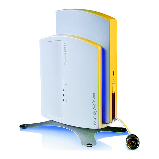
MP.11 5054 (MP.11a) Installation and Management Introduction The Tsunami MP.11 Model 5054 (MP.11a) Base Station Unit and Subscriber Unit is a flexible wireless indoor router that lets you design solutions for point-to-point links and point-to-multipoint networks. The 5054 (MP.11a) is part of the Tsunami MP.11 product family, which is comprised of several additional products, including: •... -
Page 10: Reference Manual
Introduction MP.11 5054 (MP.11a) Installation and Management Reference Manual NOTE: If you are already familiar with this type of product, you can use the Quick Install Guide to install the unit. Reference Manual As a companion to the Installation and Management manual, the Tsunami MP.11/QB.11 Reference Manual provides the following supplemental information: •... -
Page 11: Wireless Network Topologies
Introduction MP.11 5054 (MP.11a) Installation and Management Wireless Network Topologies Wireless Network Topologies The unit can be used in various network topologies and combinations. The required equipment depends upon the wireless network topology you want to build. Make sure all required equipment is available before installing the unit. You can connect the 5054 to an outdoor antenna with an optional antenna kit. -
Page 12: Point-To-Multipoint Network
Introduction MP.11 5054 (MP.11a) Installation and Management Management and Monitoring Capabilities Point-to-Multipoint Network If you want to connect more than two buildings, you can set up a single point-to-multipoint network with a single BSU and multiple SUs, as depicted in the following figure. Up to 250 SUs can be connected to a BSU. - Page 13 Introduction MP.11 5054 (MP.11a) Installation and Management Management and Monitoring Capabilities Network Manager program using SNMP, such as HP OpenView or Castelrock’s SNMPc. The units support several Management Information Base (MIB) files that describe the parameters that can be viewed and configured using SNMP: •...
-
Page 14: Installation And Initialization
MP.11 5054 (MP.11a) Installation and Management Installation and Initialization This chapter describes the steps required to install and mount the 5054, including aligning the antenna. The installation procedure does not include the mounting and connection of antennas. See the Tsunami MP.11 Antenna Installation Guide for this information. -
Page 15: Hardware Overview
Installation and Initialization MP.11 5054 (MP11.a) Installation and Management Hardware Overview Hardware Overview The 5054 supports two power methods: an AC power outlet and Power-over-Ethernet. The power supply accepts an input AC voltage in the range of 100-240 VAC. Power-over-Ethernet The unit is equipped with a Power-over-Ethernet (PoE) module. -
Page 16: Product Package
Installation and Initialization MP.11 5054 (MP11.a) Installation and Management Product Package Product Package Each shipment includes the items in the following table. Verify that you have received all parts of the shipment. NOTE: Unless noted in this table, cables are not supplied with the unit. Tsunami MP.11 5054 (MP.11a) unit Power Adaptor Mounting Stand... - Page 17 Installation and Initialization MP.11 5054 (MP11.a) Installation and Management Product Package 15 dBi Window Antenna (included with 5054-RSU-xx-WA; available for order separately) Outdoor Antenna Mounting Quantity Description Hardware and Documentation (included with 5054-RSU-xx-WA) 2 ea L-Type Mounting Plate (top) 2 ea L-Type Mounting Plate (bottom) 6 ea.
-
Page 18: Installation Procedure
Installation and Initialization MP.11 5054 (MP11.a) Installation and Management Installation Procedure Installation Procedure IMPORTANT: Before installing and using this product, see Safety and Regulatory Compliance Information on the product CD. IMPORTANT: All units must be installed by a suitably trained professional installation technician or by a qualified installation service. - Page 19 Installation and Initialization MP.11 5054 (MP11.a) Installation and Management Installation Procedure • Step 2: Unpack Shipping Box • Step 3: Attach Base (for Desktop or Ceiling Mounting only) • Step 4: Remove Covers • Step 5: Connect the Cables • Step 6: Mount the Unit •...
-
Page 20: Step 1: Choose A Location
Installation and Initialization MP.11 5054 (MP11.a) Installation and Management Installation Procedure Step 1: Choose a Location To make optimal use of the 5054, you must find a suitable location for the hardware. The range of the unit largely depends upon the position of the antenna. Proxim recommends you do a site survey, observing the following requirements, before mounting the 5054 hardware. -
Page 21: Step 3: Attach Base (For Desktop Or Ceiling Mounting Only)
Installation and Initialization MP.11 5054 (MP11.a) Installation and Management Installation Procedure Step 3: Attach Base (for Desktop or Ceiling Mounting only) If the unit will be mounted on a desktop or to a ceiling, attach the metal base as follows. If the unit will be mounted to a wall, proceed to Step 4: Remove Covers. -
Page 22: Step 4: Remove Covers
Installation and Initialization MP.11 5054 (MP11.a) Installation and Management Installation Procedure Step 4: Remove Covers In order to cable the unit for operation, you must first remove the front, back, and cable covers. 1. Unlock the unit’s cable cover by pressing down on the cable cover lock located on the side of the unit. 2. -
Page 23: Step 5: Connect The Cables
Installation and Initialization MP.11 5054 (MP11.a) Installation and Management Installation Procedure Step 5: Connect the Cables 1. Identify the location at which you intend to mount the unit. 2. Connect the grounding wire to the 5054 using the Faston plug on the metal case, next to the power plug. Location of Faston plug 3. -
Page 24: Step 6: Mount The Unit
Installation and Initialization MP.11 5054 (MP11.a) Installation and Management Installation Procedure Step 6: Mount the Unit • Desktop Mount • Wall Mount • Ceiling Mount Desktop Mount 1. Fit the radio inside the back cover, with the serial connection and LED indicators facing out. 2. - Page 25 Installation and Initialization MP.11 5054 (MP11.a) Installation and Management Installation Procedure Wall Mount 1. Place the back cover on the mounting location and mark the center of the three mounting holes. Mounting holes 2. Remove the cover from the wall and drill a hole at each of the locations you marked. Each hole should be wide enough to hold a mounting plug (6 mm x 35 mm).
- Page 26 Installation and Initialization MP.11 5054 (MP11.a) Installation and Management Installation Procedure Ceiling Mount 1. Fit the radio inside the back cover, with the serial connection and LED indicators facing out. 2. Replace the front cover, threading the cables through the opening at the lower right side of the cover. 3.
- Page 27 Installation and Initialization MP.11 5054 (MP11.a) Installation and Management Installation Procedure 4. If you have not done so before, attach the metal base as described in Step 3: Attach Base (for Desktop or Ceiling Mounting only). 5. Feed a mounting screw through each of the four rubber feet. The 5054 comes with four 3.5 mm x 40 mm pan-head screws.
-
Page 28: Step 7: Power On The Unit
Installation and Initialization MP.11 5054 (MP11.a) Installation and Management Installation Procedure Step 7: Power on the Unit The 5054 can be powered by a power supply (just plug the power cord of the power supply into an AC power outlet), or by PoE (connect a PoE splitter to the Ethernet cabling). -
Page 29: Step 9: Align The Antenna
Installation and Initialization MP.11 5054 (MP11.a) Installation and Management Installation Procedure Step 9: Align the Antenna Antenna alignment is the process of physically aligning the antenna of the radio receiver and transmitter to have the best possible link established between them. The antenna alignment process is usually performed during installation and after major repairs. -
Page 30: Step 10: Attach Kensington Security Lock (Optional)
Installation and Initialization MP.11 5054 (MP11.a) Installation and Management Installation Procedure Step 10: Attach Kensington Security Lock (Optional) If desired, you can attach a Kensington lock to secure the cable cover into place. This protects the unit from unauthorized tampering. The 5054 enclosure includes a Kensington Security Slot for use with a Kensington locking mechanism. -
Page 31: Step 11: Install Documentation And Software
Installation and Initialization MP.11 5054 (MP11.a) Installation and Management Installation Procedure Step 11: Install Documentation and Software To install the documentation and software on a computer or network: 1. Place the CD in a CD-ROM drive. The installer normally starts automatically. (If the installation program does not start automatically, click setup.exe on the installation CD.) 2. -
Page 32: Initialization
Installation and Initialization MP.11 5054 (MP11.a) Installation and Management Initialization Initialization Connecting to the unit requires either: • A direct physical connection with an Ethernet cross-over cable or with a serial RS232C cable • A network connection Connecting with a serial connection, allows you to configure and manage the unit with the CLI. Connecting with the other connections allows you to use of the Web Interface and SNMP in addition to the CLI. - Page 33 Installation and Initialization MP.11 5054 (MP11.a) Installation and Management Initialization 3. To set the IP address manually, ensure that Static is selected as the IP Address Type and fill in the IP Address and Subnet Mask suitable for the LAN subnet to which the unit is connected. To set the IP address dynamically, ensure that Dynamic is selected as the IP Address Type.
-
Page 34: Logging In To The Web Interface
Installation and Initialization MP.11 5054 (MP11.a) Installation and Management Logging in to the Web Interface Logging in to the Web Interface The Web Interface provides a graphical user interface through which you can easily configure and manage the unit. This section describes only how to access the Web Interface. -
Page 35: System Overview
MP.11 5054 (MP11.a) Installation and Management System Overview This chapter provides an overview of the system. See the following sections: • Changing Basic Configuration Information – Country and Related Settings – Dynamic Frequency Selection (DFS) – Transmit Power Control • SU Registration •... -
Page 36: Dynamic Frequency Selection (Dfs)
System Overview MP.11 5054 (MP.11a) Installation and Management Changing Basic Configuration Information NOTE: Non-US installers should not add an antenna system until the Country is selected, the unit is rebooted, and the proper power level is configured. The output power level of the final channel selected by DFS scan can be found in the Event Log. -
Page 37: Transmit Power Control
System Overview MP.11 5054 (MP.11a) Installation and Management Changing Basic Configuration Information 1. Radar avoidance both at startup and while operational. To meet these requirements, the BSU scans available frequencies at startup. If a DFS-enabled channel is busy or occupied with radar, the system will blacklist the channel for a period of 30 minutes in accordance with FCC, IC, and ETSI regulations. -
Page 38: Su Registration
System Overview MP.11 5054 (MP.11a) Installation and Management SU Registration SU Registration The list of parameters you must configure for registration of the SU on a BSU are: • Network Name • Base Station System Name (when used; otherwise, leave blank) •... -
Page 39: Dynamic Data Rate Selection (Ddrs)
System Overview MP.11 5054 (MP.11a) Installation and Management Dynamic Data Rate Selection (DDRS) Dynamic Data Rate Selection (DDRS) The WORP Dynamic Data Rate Selection (DDRS) lets the BSU and SUs monitor the remote average signal-to-noise ratio (SNR) and the number of retransmissions between the BSU and SUs and adjust the transmission data rate to an optimal value to provide the best possible throughput according to the current communication conditions and link quality. -
Page 40: Virtual Local Area Networks (Vlans)
System Overview MP.11 5054 (MP.11a) Installation and Management Virtual Local Area Networks (VLANs) Virtual Local Area Networks (VLANs) Virtual Local Area Networks (VLANs) are logical groupings of network hosts. Defined by software settings, other VLAN members or resources appear (to connected hosts) to be on the same physical segment, no matter where they are attached on the logical LAN or WAN segment. -
Page 41: Quality Of Service (Qos)
System Overview MP.11 5054 (MP.11a) Installation and Management Quality of Service (QoS) Quality of Service (QoS) The Quality of Service (QoS) feature is based on the 802.16 standard and defines the classes, service flows, and packet identification rules for specific types of traffic. QoS main priority is to guarantee a reliable and adequate transmission quality for all types of traffic under conditions of high congestion and bandwidth over-subscription. - Page 42 System Overview MP.11 5054 (MP.11a) Installation and Management Quality of Service (QoS) a. Protocol Destination Port Range (8000-8001, 10000-20000) b. IP Protocol List (17 = UDP) 6. TCP a. IP Protocol List (6) 7. UDP a. IP Protocol List (17) 8.
- Page 43 System Overview MP.11 5054 (MP.11a) Installation and Management Quality of Service (QoS) • Minimum reserved traffic rate (or Committed Information Rate, CIR) – specified in units of 1 Kbps from 0 Kbps up to the maximum rate of 10000 Kbps per SU •...
- Page 44 System Overview MP.11 5054 (MP.11a) Installation and Management Quality of Service (QoS) g. Traffic Priority = 1 Note that two different VoIP Service Flow classes for each direction of traffic have been defined (index numbers 3 to 6), which follow the ITU-T standard nomenclatures: G.711 refers to a type of audio companding and encoding that produces a 64 Kbps bitstream, suitable for all types of audio signals.
-
Page 45: Basic Management
MP.11 5054 (MP.11a) Installation and Management Basic Management This chapter describes basic features and functionality of the unit. In most cases, configuring these basic features is sufficient. The “Glossary” in the Tsunami MP.11/QB.11 Reference Manual provides a brief explanation of the terms used. For CLI commands you can use for basic management, see “Command Line Interface”... -
Page 46: Rebooting And Resetting
Basic Management MP.11 5054 (MP11.a) Installation and Management Rebooting and Resetting Rebooting and Resetting All configuration changes require a restart unless otherwise stated. You can restart the unit with the Reboot command; see Rebooting, below). Most changes you make become effective only when the unit is rebooted. A reboot stores configuration information in non-volatile memory and then restarts the unit with the new values (see Soft Reset to Factory Default). -
Page 47: Soft Reset To Factory Default
Basic Management MP.11 5054 (MP11.a) Installation and Management Rebooting and Resetting Soft Reset to Factory Default If necessary, you can reset the unit to the factory default settings. This should be done only when you are experiencing problems. Resetting to the default settings requires you to reconfigure the unit. To reset to factory default settings: 1. -
Page 48: General Configuration Settings
Basic Management MP.11 5054 (MP11.a) Installation and Management General Configuration Settings General Configuration Settings • System Status: The Status tab showing the system status is displayed automatically when you log into the Web interface. It is also the default window displayed when you click the Status button on the left side of the window. See System Status. -
Page 49: Monitoring Settings
Basic Management MP.11 5054 (MP11.a) Installation and Management Monitoring Settings Monitoring Settings The unit offers various facilities to monitor its operation and interfaces. Only the most significant monitoring categories are mentioned here. • Wireless: To monitor the wireless interfaces, click Monitor > Wireless. This tab lets you monitor the general performance of the radio and the performance of the WORP Base or WORP Satellite interfaces. -
Page 50: Security Settings
Basic Management MP.11 5054 (MP11.a) Installation and Management Security Settings Security Settings To prevent misuse, the 5054 provide wireless data encryption and password-protected access. Be sure to set the encryption parameters and change the default passwords. In addition to Wired Equivalent Privacy (WEP), the units support Advanced Encryption Standard (AES) 128-bit encryption. -
Page 51: Default Settings
Basic Management MP.11 5054 (MP11.a) Installation and Management Default Settings Default Settings Feature Default System Name Tsunami MP.11 5054 Mode of Operation Bridge Routing Disabled IP Address Assignment Type Static IP Address 10.0.0.1 Subnet Mask 255.255.255.0 Default Router IP Address 10.0.0.1 Default TTL RIPv2... - Page 52 Basic Management MP.11 5054 (MP11.a) Installation and Management Default Settings Feature Default Broadcast Protocol Filtering All Protocols Allowed Dynamic Data Rate Selection Disabled Roaming Disabled Disabled Intra-Cell Blocking Disabled Antenna Alignment Disabled Country Selection US-only device – US World device – GB DHCP Server Disabled DHCP Relay...
-
Page 53: Upgrading The Unit
Basic Management MP.11 5054 (MP11.a) Installation and Management Upgrading the Unit Upgrading the Unit The units are equipped with embedded software that can be updated when new versions are released. Updating the embedded software is described in Web Interface Image File Download. -
Page 54: System Status
MP.11 5054 (MP.11a) Installation and Management System Status This chapter describes viewing system status and event log information from the unit’s Web Interface. Click on the Status button to access system and event log information. See the following sections: • Status •... -
Page 55: Event Log
System Status MP.11 5054 (MP.11a) Installation and Management Event Log Event Log Click Status > Event Log to view the contents of your Event Log. The Event Log keeps track of events that occur during the operation of the unit. The Event Log displays messages that may not be captured by System Traps, such as the Transmit Power for the Frequency Channel selected. -
Page 56: Configuration
MP.11 5054 (MP.11a) Installation and Management Configuration This chapter describes the unit’s settings using the unit’s Web Interface. Click the Configure button to access configuration settings. The following topics are discussed in this chapter: • System Parameters • Network Parameters •... - Page 57 Configuration MP.11 5054 (MP.11a) Installation and Management System Parameters You can view or enter the following details: • System Name: This is the system name for easy identification of the BSU or SU. The System Name field is limited to a length of 32 bytes.
-
Page 58: Bridge And Routing Modes
Configuration MP.11 5054 (MP.11a) Installation and Management System Parameters • Mode of Operation: This drop-down menu is used to set the unit as a bridge (layer 2) or as a router (layer 3). See Bridge and Routing Modes for more information. Bridge and Routing Modes Bridge Mode A bridge is a product that connects a local area network (LAN) to another LAN that uses the same protocol (for example,... - Page 59 Configuration MP.11 5054 (MP.11a) Installation and Management System Parameters on the way to your connection to the Internet. You can configure routes to other networks on your Intranet through the addition of static routes in your router’s routing table. Key Reasons to Use Routing Mode One key reason why customers would use Routing mode is to implement virtual private networks (VPNs) or to let nodes behind two different SUs communicate with each other.
- Page 60 Configuration MP.11 5054 (MP.11a) Installation and Management System Parameters Notes: • One of the most important details to pay attention to in Routing mode are the unit’s and the PC’s default gateways. It is a common mistake to set up the PC’s gateway to point to the SU when the SU is in Bridge mode and the BSU is in Routing mode.
-
Page 61: Network Parameters
Configuration MP.11 5054 (MP.11a) Installation and Management Network Parameters Network Parameters The Network tab contains the following sub-tabs. Note that the availability of some sub-tabs depends on whether the unit is in Bridge or Routing Mode. • IP Configuration • Roaming •... -
Page 62: Roaming
Configuration MP.11 5054 (MP.11a) Installation and Management Network Parameters Routing Mode If the device is configured in Routing mode, both Ethernet and Wireless interfaces require an IP address. The following screen is displayed: Configure or view the following parameters: • IP Address Ethernet Port: The unit’s Ethernet IP address. - Page 63 Configuration MP.11 5054 (MP.11a) Installation and Management Network Parameters Roaming can only occur if the normal scanning or fast scanning procedure is started under the following conditions: 1. If the roaming is started from the normal scanning procedure (after the SU scans all the active channels), the SU selects the BSU with the best SNR value on all available channels.
- Page 64 Configuration MP.11 5054 (MP.11a) Installation and Management Network Parameters BSU Roaming Configuration View or set the following parameters: • Enable Roaming Status: Enable or disable the Roaming feature by selecting or de-selecting the checkbox. The default value is disabled (clear). •...
-
Page 65: Dhcp Server
Configuration MP.11 5054 (MP.11a) Installation and Management Network Parameters SU Roaming Configuration Enable or disable the Roaming feature in the Roaming Status drop-down box. The default value is disabled. NOTE: To enable roaming, you must enable Roaming Status on both the BSU and the SU. DHCP Server When enabled, the DHCP server allows allocation of IP addresses to hosts on the Ethernet side of the SU or BSU. - Page 66 Configuration MP.11 5054 (MP.11a) Installation and Management Network Parameters NOTE: There must be at least one entry in the DHCP server IP Pool Table to enable DHCP server. Also, DHCP server cannot be enabled if DHCP Relay Agent is enabled. •...
-
Page 67: Spanning Tree (Bridge Mode Only)
Configuration MP.11 5054 (MP.11a) Installation and Management Network Parameters Spanning Tree (Bridge Mode Only) NOTE: The unit must be in Bridge mode to configure Spanning Tree. This protocol is executed between the bridges to detect and logically remove redundant paths from the network. Spanning Tree can be used to prevent link-layer loops (broadcast is forwarded to all port where another device may forward it and, finally, it gets back to this unit;... -
Page 68: Ip Routes (Routing Mode Only)
Configuration MP.11 5054 (MP.11a) Installation and Management Network Parameters IP Routes (Routing Mode Only) NOTE: The unit must be in Routing mode to configure IP Routes. Click Configure > Network > IP Routes to configure. Add IP Routes 1. Click the Add button; the following screen is displayed. 2. -
Page 69: Dhcp Relay Agent (Routing Mode Only)
Configuration MP.11 5054 (MP.11a) Installation and Management Network Parameters Edit/Delete IP Routes 1. Click the Edit/Delete Table Entries button. 2. Edit the route information. 3. Click OK. The IP address and subnet mask combination is validated for a proper combination. DHCP Relay Agent (Routing Mode Only) NOTE: The unit must be in Routing mode to configure DHCP Relay Agent. - Page 70 Configuration MP.11 5054 (MP.11a) Installation and Management Network Parameters 2. Enter the Server IP Address and any optional comments, and click Add. Edit/Delete Entries in the DHCP Relay Agent Table To edit or delete entries in the table of DHCP Relay Agents: 1.
-
Page 71: Interface Parameters
Configuration MP.11 5054 (MP.11a) Installation and Management Interface Parameters Interface Parameters The Interface tab contains the following sub-tabs. • Wireless – Base Mode – Satellite Mode • Ethernet Wireless To configure the wireless interface, click Configure > Interfaces > Wireless. For Base Station units, the wireless interface can be placed in either WORP Base or WORP Satellite mode (selected from the Interface Type drop-down box). - Page 72 Configuration MP.11 5054 (MP.11a) Installation and Management Interface Parameters Base Mode The following parameters may be configured or viewed: • Interface Type: The interface type can be WORP Satellite or WORP Base. • MAC Address: The factory-assigned MAC address of the unit. This is a read-only field. •...
- Page 73 Configuration MP.11 5054 (MP.11a) Installation and Management Interface Parameters NOTE: This feature only lets you decrease your output power; it does not let you increase your output power beyond the maximum allowed defaults for your frequency and country. Select one of the following options and click OK at the bottom of the window. Your original output power is adjusted relative to the value selected.
- Page 74 Configuration MP.11 5054 (MP.11a) Installation and Management Interface Parameters Multicast Rates in Mbps with Multicast Rates in Mbps Turbo Mode Enabled (Non-DFS US Only) 54 (see note) 108 (see note) NOTE: If you select 48 or 54 Mbps (96 or 108 in Turbo mode) DDRS is automatically turned on. •...
- Page 75 Configuration MP.11 5054 (MP.11a) Installation and Management Interface Parameters • No-Sleep Mode: No-Sleep Mode was a feature used to control jitter in Tsunami MP.11 products running 2.2.6, and earlier, versions of software. The introduction of QoS and the new WORP resource scheduling mechanism have eliminated the need for No-Sleep Mode.
- Page 76 Configuration MP.11 5054 (MP.11a) Installation and Management Interface Parameters • DDRS Default Data Rate: The data rate at which the BSU starts communication with all SUs to begin the registration process (the default is 6 Mbps). This data rate is configured on the BSU only. •...
- Page 77 Configuration MP.11 5054 (MP.11a) Installation and Management Interface Parameters Appears only when selected country requires • DFS Preferred Channel: A single DFS preferred frequency channel on the BSU is provided so that when the DFS process starts the BSU will first try the DFS preferred channel before scanning all the other active channels in the DFS channel list.
- Page 78 Configuration MP.11 5054 (MP.11a) Installation and Management Interface Parameters In accordance with ETSI, IC, and FCC non-occupancy rules, when interference is detected on any active channel, that channel will be blacklisted. The channel will not be used for a period of 30 minutes after the interference has been detected.
- Page 79 Configuration MP.11 5054 (MP.11a) Installation and Management Interface Parameters Satellite Mode The mandatory parameters to configure for registration of the SU on a Base Station are: • Network Name • Base Station System Name (when used) • Channel Frequency • Encryption (when used) •...
- Page 80 Configuration MP.11 5054 (MP.11a) Installation and Management Interface Parameters • Transmit Power Control (TPC): By default, the unit lets you transmit at the maximum output power for the country/ band or regulatory domain and frequency selected. However, with Transmit Power Control (TPC), you can adjust the output power of the unit to a lower level in order to reduce interference to neighboring devices or to use a higher gain antenna without violating the maximum radiated output power allowed for your country/band.
- Page 81 Configuration MP.11 5054 (MP.11a) Installation and Management Interface Parameters Multicast Rates in Mbps Multicast Rates in Mbps with Turbo Mode Enabled (Non-DFS US Only) • Channel Bandwidth: This is a read only field. Channel Bandwidth is set at 20 MHz. •...
-
Page 82: Ethernet
Configuration MP.11 5054 (MP.11a) Installation and Management Interface Parameters Ethernet To set the Ethernet speed, duplex mode, and input and output bandwidth limits, click Configure > Interfaces > Ethernet. You can set the desired speed and transmission mode by clicking on Configuration. Select from these settings for the type of Ethernet transmission: •... -
Page 83: Snmp Parameters
Configuration MP.11 5054 (MP.11a) Installation and Management SNMP Parameters SNMP Parameters Click Configure > SNMP to enable or disable trap groups, and to configure the SNMP management stations to which the unit sends system traps. See “Trap Groups” in the Tsunami MP.11/QB.11 Reference Manual for a list of the system traps. •... - Page 84 Configuration MP.11 5054 (MP.11a) Installation and Management SNMP Parameters...
-
Page 85: Management Parameters
Configuration MP.11 5054 (MP.11a) Installation and Management Management Parameters Management Parameters Use the Management tab to configure passwords and other service parameters. Passwords The Password tab lets you configure the SNMP, Telnet, and HTTP (Web Interface) passwords. For all password fields, the passwords must be between 6 and 32 characters. Changes take effect immediately after you click OK. - Page 86 Configuration MP.11 5054 (MP.11a) Installation and Management Management Parameters SNMP Configuration Settings • SNMP Interface Bitmask: Configure the interface or interfaces (All Interfaces, Only Ethernet, Only Slot A, None) from which you will manage the unit using SNMP. You also can select Disabled to prevent a user from accessing the unit through SNMP.
- Page 87 Configuration MP.11 5054 (MP.11a) Installation and Management Management Parameters Serial Configuration Settings The serial port interface on the unit is enabled at all times. See “Serial Port” in the Tsunami MP.11/QB.11 Reference Manual for information about how to access the CLI interface through the serial port. You can configure and view following parameters: •...
-
Page 88: Security Parameters
Configuration MP.11 5054 (MP.11a) Installation and Management Security Parameters Security Parameters MAC Authentication (BSU Only) Click Configure > Security > MAC Auth to build a list of authorized wireless stations that can register at the unit and access the network. MAC Authentication is supported on the wireless interface and only wireless MAC addresses should be entered in the list. -
Page 89: Encryption
Configuration MP.11 5054 (MP.11a) Installation and Management Security Parameters Encryption NOTE: Be sure to set the encryption parameters and change the default passwords. You can protect the wireless data link by using encryption. In addition to Wi-Fi Protected Access (WPA) and Wired Equivalent Privacy (WEP), the unit supports Advanced Encryption Standard (AES) 128-bit encryption. - Page 90 Configuration MP.11 5054 (MP.11a) Installation and Management Security Parameters...
-
Page 91: Filtering Parameters
Configuration MP.11 5054 (MP.11a) Installation and Management Filtering Parameters Filtering Parameters Overview Click Configure > Filtering to configure packet filtering. Packet filtering can be used to control and optimize network performance. The Filtering feature can selectively filter specific packets based upon their Ethernet protocol type. Protocol filtering is done at the Bridge layer. -
Page 92: Ethernet Protocol
Configuration MP.11 5054 (MP.11a) Installation and Management Filtering Parameters consume valuable wireless bandwidth. On some networks, there are so many ARP broadcasts that the performance of the wireless network will degrade due to the amount of bandwidth being consumed by these messages. To reduce the number of ARP broadcasts that are forwarded to the wireless nodes, you can enable ARP filtering. -
Page 93: Static Mac Address Filtering
Configuration MP.11 5054 (MP.11a) Installation and Management Filtering Parameters – Enter the Protocol Number. See http://www.iana.org/assignments/ethernet-numbers for a list of protocol numbers. – Enter the Protocol Name. – Click Add. Edit/Delete Entries in the Filter Table 1. Click Edit and change the information, or select Enable, Disable, or Delete from the Status drop-down menu. Static MAC Address Filtering Overview The Static MAC Address filter optimizes the performance of a wireless (and wired) network. - Page 94 Configuration MP.11 5054 (MP.11a) Installation and Management Filtering Parameters • Wired Server: 00:40:F4:1C:DB:6A • Wireless Client 1: 00:02:2D:51:94:E4 • Wireless Client 2: 00:02:2D:51:32:12 • Wireless Client 3: 00:20:A6:12:4E:38 Prevent Two Specific Devices from Communicating Configure the following settings to prevent the Wired Server and Wireless Client 1 from communicating: •...
- Page 95 Configuration MP.11 5054 (MP.11a) Installation and Management Filtering Parameters network use a specific multicast address (such as 01:00:5E:00:32:4B) to exchange information, you can set up a filter to prevent these multicast packets from being forwarded to the wireless network: • Wired MAC Address: 01:00:5E:00:32:4B •...
-
Page 96: Storm Threshold
Configuration MP.11 5054 (MP.11a) Installation and Management Filtering Parameters • Wireless Mask: Enter the appropriate bit mask to specify the range of MAC addresses to which this filter is to apply. To specify only the single MAC address you entered in the Wireless MAC Address field, enter 00:00:00:00:00:00 (all zeroes). -
Page 97: Ip Access Table Filtering
Configuration MP.11 5054 (MP.11a) Installation and Management Filtering Parameters Click the Edit Table Entries button to display an editable window such as the following. You can configure whether this traffic must be blocked for Ethernet to wireless, wireless to Ethernet, or both. IP Access Table Filtering Click Configure >... - Page 98 Configuration MP.11 5054 (MP.11a) Installation and Management Filtering Parameters Add Entries to the IP Access Table To add an entry, click the Add Table Entries button, specify the IP address and mask of the wireless stations to which you want to grant access, and click Add. CAUTION: Ensure that the IP address of the management PC you use to manage the unit is within the first entry in the table, as this filter takes effect immediately.
-
Page 99: Intra-Cell Blocking (Bsu Only; Bridge Mode Only)
Configuration MP.11 5054 (MP.11a) Installation and Management Intra-Cell Blocking (BSU Only; Bridge Mode Only) Intra-Cell Blocking (BSU Only; Bridge Mode Only) Overview The Intra-Cell Blocking feature lets traffic be blocked between two SUs registered to the same Base Station. There are two potential reasons to isolate traffic among wireless subscribers: •... - Page 100 Configuration MP.11 5054 (MP.11a) Installation and Management Intra-Cell Blocking (BSU Only; Bridge Mode Only) The following items are configurable: • Intra-Cell Blocking Status: Enables or disables the Intra-Cell Blocking feature. • Group Table: Entries in this table show the Intra-Cell Blocking filter groups that have been configured. When Intra- Cell Blocking is enabled, the Base Station Unit discards all packets coming from one SU to another SU, if both SUs do not belong to the same filter group.
-
Page 101: Mac Table
Configuration MP.11 5054 (MP.11a) Installation and Management Intra-Cell Blocking (BSU Only; Bridge Mode Only) MAC Table After configuring the Intra-Cell Blocking Groups on the Group Table tab, use the MAC Table tab to assign specific MAC addresses to an Intra-Cell Blocking Group. Adding Entries Click the Add Table Entries button. -
Page 102: Security Gateway
Configuration MP.11 5054 (MP.11a) Installation and Management Intra-Cell Blocking (BSU Only; Bridge Mode Only) Security Gateway You can configure a Security Gateway to block traffic between SUs connected to different BSUs. Verify that Intra-Cell Blocking has been enabled on the Group Table tab before configuring the Security Gateway. •... -
Page 103: Vlan Parameters (Bsu Only; Bridge Mode Only)
Configuration MP.11 5054 (MP.11a) Installation and Management VLAN Parameters (BSU Only; Bridge Mode Only) VLAN Parameters (BSU Only; Bridge Mode Only) Overview For an introduction to VLAN principles, see Virtual Local Area Networks (VLANs) in the System Overview chapter. NOTE: VLANs are configurable only in Bridge mode. VLAN Modes Transparent Mode Transparent mode is available on both the SU and the BSU. - Page 104 Configuration MP.11 5054 (MP.11a) Installation and Management VLAN Parameters (BSU Only; Bridge Mode Only) VLAN Relaying The VLAN Trunk mode for BSU operation provides an option to enable and disable a VLAN relaying flag; when enabled, the BSU shall relay frames between SUs on the same BSU having the same VLAN ID. Management VLAN The BSU and SU allow the configuration of a separate VLAN ID and priority for SNMP, ICMP, Telnet, and TFTP management frames for device access.
- Page 105 Configuration MP.11 5054 (MP.11a) Installation and Management VLAN Parameters (BSU Only; Bridge Mode Only) BSU in Trunk Mode and SU in Trunk/Access Mode When the BSU is in Trunk mode, the associated SUs must be in either Trunk mode or Access mode. When an SU associates to a BSU that is in Trunk mode, it gets the VLAN mode from the BSU.
- Page 106 Configuration MP.11 5054 (MP.11a) Installation and Management VLAN Parameters (BSU Only; Bridge Mode Only) BSU in Mixed Mode and SU in Mixed, Access, or Trunk Mode When the BSU is in Mixed mode, the associated SUs can be in Trunk, Access, or Mixed mode. How the BSU and SU function in Trunk mode, and the SU in Access mode and Mixed mode, is described in the following table:...
- Page 107 Configuration MP.11 5054 (MP.11a) Installation and Management VLAN Parameters (BSU Only; Bridge Mode Only) BSU Function – Mixed SU Function – Mixed Mode SU Function – Trunk Mode SU Function – Access Mode Mode • Up to 256 VLAN IDs can •...
-
Page 108: Bsu Vlan Configuration
Configuration MP.11 5054 (MP.11a) Installation and Management VLAN Parameters (BSU Only; Bridge Mode Only) BSU VLAN Configuration The HTTP Interface to configure BSU VLAN parameters is shown in the following figure. Configure the following parameters: • BSU VLAN Mode: The BSU VLAN mode can be either Transparent, Trunk, or Mixed. By default, the BSU is in Transparent mode. -
Page 109: Su Vlan Configuration
Configuration MP.11 5054 (MP.11a) Installation and Management VLAN Parameters (BSU Only; Bridge Mode Only) Edit or Delete BSU VLAN Table Entries To edit or delete entries in the BSU VLAN Table, click the Edit/Delete Table Entries button, make your changes, then click OK for your changes to take effect. - Page 110 Configuration MP.11 5054 (MP.11a) Installation and Management VLAN Parameters (BSU Only; Bridge Mode Only) Add SU Table Entries To add entries to the SU VLAN Table, click the Add Table Entries button. Enter the desired parameters in the corresponding fields, then click Add to add and save the entry. The following parameters are configurable: •...
- Page 111 Configuration MP.11 5054 (MP.11a) Installation and Management VLAN Parameters (BSU Only; Bridge Mode Only) NOTE: When the BSU is changed to Mixed mode, all the configured SUs are changed to Mixed mode by default. You may then configure SUs for Access or Trunk mode as needed. •...
-
Page 112: Qos (Quality Of Service) Parameters (Bsu Only)
Configuration MP.11 5054 (MP.11a) Installation and Management QoS (Quality of Service) Parameters (BSU Only) QoS (Quality of Service) Parameters (BSU Only) The Quality of Service (QoS) feature is based on 802.16 standard and defines the classes, service flows (SFCs), and packet identification rules (PIRs) for specific types of traffic. -
Page 113: Qos Sfc Configuration
Configuration MP.11 5054 (MP.11a) Installation and Management QoS (Quality of Service) Parameters (BSU Only) To add entries to the PIR Table, click the Add Table Entries button. Enter the Rule Name and select Enable or Disable from the Entry Status drop-down box, then click Add to add the entry. Once the new entry appears in the QoS PIR Table on this page, click its Details button to view/edit its parameters. - Page 114 Configuration MP.11 5054 (MP.11a) Installation and Management QoS (Quality of Service) Parameters (BSU Only) To add entries to the SFC Table, click the Add Table Entries button. The following parameters are configurable: • SF Name: Enter the name of the SF class you want to add. •...
-
Page 115: Qos Class Configuration
Configuration MP.11 5054 (MP.11a) Installation and Management QoS (Quality of Service) Parameters (BSU Only) No. of messages in a burst: % of the maximum throughput: 100% 97.6% 92.9% 76.2% • SF Entry State: This field can be set to Enable, Disable, or Delete. Click Add to add the entry. - Page 116 Configuration MP.11 5054 (MP.11a) Installation and Management QoS (Quality of Service) Parameters (BSU Only) The following parameters are configurable: • Class Name: Enter the name of the QoS class you want to add. • SF Table Reference Index: Select one of the possible SFCs that have been previously configured from the drop- down box to associate to this QoS Class.
- Page 117 Configuration MP.11 5054 (MP.11a) Installation and Management QoS (Quality of Service) Parameters (BSU Only) You may enable, disable or delete this QoS Class entry by clicking on the Status drop-down box and then clicking OK. You may also edit an existing SFC associated to this QoS class, or associate a new SFC to this QoS class. See the following sections.
- Page 118 Configuration MP.11 5054 (MP.11a) Installation and Management QoS (Quality of Service) Parameters (BSU Only) Configure the following parameters: • PIR Table Reference Index: Select one of the possible PIRs that have been previously configured from the drop- down box. • PIR Priority: This priority per rule defines the order of execution of PIRs during packet identification process.
-
Page 119: Qos Su Configuration
Configuration MP.11 5054 (MP.11a) Installation and Management QoS (Quality of Service) Parameters (BSU Only) The following parameters are configurable: • SF Table Reference Index: Select one of the possible SFCs that have been previously configured from the drop- down box to associate to this QoS Class. •... -
Page 120: Qos Configuration For A Management Station
Configuration MP.11 5054 (MP.11a) Installation and Management QoS (Quality of Service) Parameters (BSU Only) Enter the following information: • SU MAC Address: The MAC Address of the SU you want to associate to a specific QoS Class. • SU QOSC Index: Select one of the possible QoS Classes that have been previously configured from the drop-down box to associate to this SU. - Page 121 Configuration MP.11 5054 (MP.11a) Installation and Management QoS (Quality of Service) Parameters (BSU Only) The configuration instructions that follow explain how to configure the system so that configuration parameters can always be changed, and ping requests and responses get higher priority in order to show the actual connectivity of the pinged node.
- Page 122 Configuration MP.11 5054 (MP.11a) Installation and Management QoS (Quality of Service) Parameters (BSU Only) • IP Mask or MAC Mask: 255.255.255.255 (for IP Mask) or FF:FF:FF:FF:FF:FF (for MAC mask) 9. Click Add. 10. Return to the QoS PIR tab, and click Add Table Entries. 11.
- Page 123 Configuration MP.11 5054 (MP.11a) Installation and Management QoS (Quality of Service) Parameters (BSU Only) • Priority: 7 • Number of Frames Per Burst: 4 • SF Entry State: Enable 2. Click Add. The UL-Management SF will be added to the QoS Service Flow Table. NOTE: The input and output bandwidth limits set on the BSU or on the SU are used for limiting aggregate bandwidth used by singe SU.
- Page 124 Configuration MP.11 5054 (MP.11a) Installation and Management QoS (Quality of Service) Parameters (BSU Only) • Entry Status: Enable 8. Return to the QoS Class screen and repeat steps 2 - 6 for the UL-Management SF in this class. 9. Return to the QoS Class screen and repeat steps 1 - 8 for any other QoS Classes used in the network.
-
Page 125: Rip Parameters (Routing Mode Only)
Configuration MP.11 5054 (MP.11a) Installation and Management RIP Parameters (Routing Mode Only) RIP Parameters (Routing Mode Only) Routing Internet Protocol (RIP) is a dynamic routing protocol you can use to help automatically propagate routing table information between routers. The unit can be configured as RIPv1, RIPv2, RIPv1 Compatible, or a combination of the three versions while operating in Routing mode. -
Page 126: Rip Example
Configuration MP.11 5054 (MP.11a) Installation and Management RIP Parameters (Routing Mode Only) RIPv1 RIPv2 RIPv1 Compatible Maximum Distance 15 Maximum Distance 15 Maximum Distance 15 RIP Example In the following example, assume that both the BSU and the SUs all are configured in Routing mode with RIP enabled to send and receive on both the Ethernet and Wireless interfaces. -
Page 127: Nat (Su Only; Routing Mode Only)
Configuration MP.11 5054 (MP.11a) Installation and Management NAT (SU Only; Routing Mode Only) NAT (SU Only; Routing Mode Only) The NAT (Network Address Translation) feature lets hosts on the Ethernet side of the SU transparently access the public network through the BSU. All hosts in the private network can have simultaneous access to the public network. NOTE: The NAT tab is available for SUs in Routing mode only. -
Page 128: Supported Session Protocols
Configuration MP.11 5054 (MP.11a) Installation and Management NAT (SU Only; Routing Mode Only) Add Entries to the NAT Static Port Mapping Table 1. Click the Add Table Entries button. 2. Enter the following information, and click Add: • Enter the Local IP Address of the host on the Ethernet side of the SU. •... - Page 129 Configuration MP.11 5054 (MP.11a) Installation and Management NAT (SU Only; Routing Mode Only) Protocol Support Applications Limitations H.323 H.323 ALG Multimedia conferencing HTTP Port mapping for inbound Web browser connection. TFTP Port mapping for inbound File transfer connection. Telnet Port mapping for inbound Remote login connection.
-
Page 130: Monitoring
MP.11 5054 (MP.11a) Installation and Management Monitoring This chapter describes using the Web interface to obtain detailed information about the settings and performance of the unit. Click the Monitor button to access this information. The following tabs appear in the Monitor section: •... -
Page 131: Wireless
Monitoring MP.11 5054 (MP.11a) Installation and Management Wireless Wireless General Performance Click Monitor > Wireless > General to monitor the general performance of the wireless interface. WORP Interface Performance Click Monitor > Wireless > WORP tab to monitor the performance of the WORP Base or WORP SU interfaces. The Registration Last Reason field indicates either a successful registration (a value of 1) or it indicates the reason why the last registration failed. - Page 132 Monitoring MP.11 5054 (MP.11a) Installation and Management Wireless • Authentication failure • Roaming • No response from SU within the Registration Timeout Period • Low Signal Quality...
-
Page 133: Icmp
Monitoring MP.11 5054 (MP.11a) Installation and Management ICMP ICMP Click Monitor > ICMP to view the number of ICMP messages sent and received by the unit. It includes ping, route, and host unreachable messages. -
Page 134: Per Station
Monitoring MP.11 5054 (MP.11a) Installation and Management Per Station Per Station Click Monitor > Per Station to view Station Statistics. On the BSU, this page shows statistics of all the SU’s connected to the BSU. The page’s statistics refresh every 4 seconds. To stop or stop the page refreshing, use the Stop Refresh and Start Refresh buttons. -
Page 135: Features
Monitoring MP.11 5054 (MP.11a) Installation and Management Features Features Click Monitor > Features to view the following information. NOTE: A BSU shows how many WORP SUs it can support; the SU shows how many Ethernet hosts it supports on its Ethernet port as the “Max Users on Satellite”... -
Page 136: Link Test
Monitoring MP.11 5054 (MP.11a) Installation and Management Link Test Link Test Click Monitor > Link Test to find out which wireless stations are in range and to check their link quality. NOTE: Link Test requires Internet Explorer version 6.0 or later. Earlier versions do not support Link Test. Link Test for the unit reports the Signal-to-Noise Ratio (SNR) value in dB;... -
Page 137: Interfaces
Monitoring MP.11 5054 (MP.11a) Installation and Management Interfaces Interfaces Click Monitor > Interfaces to view detailed information about the IP-layer performance of the unit’s interfaces. There are two sub-tabs: Wireless and Ethernet. The following figures show both interfaces. -
Page 138: Ip Arp Table
Monitoring MP.11 5054 (MP.11a) Installation and Management IP ARP Table IP ARP Table Click Monitor > IP ARP Table to view the mapping of the IP and MAC addresses of all radios registered at the BSU. This information is based upon the Address Resolution Protocol (ARP). -
Page 139: Ip Routes
Monitoring MP.11 5054 (MP.11a) Installation and Management IP Routes IP Routes Click Monitor > IP Routes to view all active IP routes of the unit. These can be either static or dynamic (obtained through RIP). This tab is available only in Routing mode, and you can add routes only when in Routing mode. -
Page 140: Learn Table
Monitoring MP.11 5054 (MP.11a) Installation and Management Learn Table Learn Table Click Monitor > Learn Table to view all MAC addresses the unit has detected on an interface. The Learn Table displays information relating to network bridging. It reports the MAC address for each node that the device has learned is on the network and the interface on which the node was detected. -
Page 141: Rip
Monitoring MP.11 5054 (MP.11a) Installation and Management Click Monitor > RIP to view Routing Internet Protocol data for the Ethernet and Wireless interfaces. -
Page 142: Radius (Bsu Only)
Monitoring MP.11 5054 (MP.11a) Installation and Management RADIUS (BSU Only) RADIUS (BSU Only) Click Monitor > Radius to view information about the traffic exchanged with a RADIUS server. -
Page 143: Qos (Bsu Only)
Monitoring MP.11 5054 (MP.11a) Installation and Management QoS (BSU Only) QoS (BSU Only) Click Monitor > QoS to view summary information about the Quality of Service per BSU and for each SU registered with that BSU. -
Page 144: Commands
MP.11 5054 (MP.11a) Installation and Management Commands This chapter describes the commands that you can issue with the Web Interface. Click the Commands button to access available commands. See the following: • Download • Upload • Reboot • Reset • Help Link •... -
Page 145: Upload
Commands MP.11 5054 (MP.11a) Installation and Management Upload Upload Click Commands > Upload to upload a configuration or log file from the unit to a TFTP server (see TFTP Server Setup for information about the SolarWinds TFTP server software located on your product installation CD). Enter the following information: •... -
Page 146: Reboot
Commands MP.11 5054 (MP.11a) Installation and Management Reboot Reboot Click Commands > Reboot to reboot the unit’s embedded software. Configuration changes are saved and the unit is reset. CAUTION: Rebooting the unit causes all users currently connected to lose their connection to the network until the unit has completed the reboot process and resumed operation. -
Page 147: Reset
Commands MP.11 5054 (MP.11a) Installation and Management Reset Reset Click Commands > Reset to restore the configuration of the unit to the factory default values. You can also reset the unit by pressing the RELOAD button located on the side of the unit. See Hard Reset to Factory Default for more information. -
Page 148: Help Link
Commands MP.11 5054 (MP.11a) Installation and Management Help Link Help Link Click Commands > Help Link to set the location of the help files of the Web Interface. Upon installation, the help files are installed in the C:\Program Files\Tsunami\MP.11 5054\Help folder. If you want to place these files on a shared drive, copy the Help folder to the new location and specify the new path in the Help Link box. -
Page 149: Downgrade
Commands MP.11 5054 (MP.11a) Installation and Management Downgrade Downgrade Click Commands > Downgrade to downgrade to a previous release. Downgrade currently is supported only to release 2.0.1 and later. Once you enter this command, the unit is downgraded to the specified release and is automatically rebooted. -
Page 150: Procedures
MP.11 5054 (MP.11a) Installation and Management Procedures This chapter describes the following procedures: • TFTP Server Setup: Prepares the TFTP server for transferring files to and from the unit. This procedure is used by the other procedures that transfer files. •... -
Page 151: Tftp Server Setup
Procedures MP.11 5054 (MP.11a) Installation and Management TFTP Server Setup TFTP Server Setup A Trivial File Transfer Protocol (TFTP) server lets you transfer files across a network. You can upload files from the unit for backup or copying, and you can download the files for configuration and image upgrades. The SolarWinds TFTP server software is located on the product installation CD, or can be downloaded from http://support.proxim.com. -
Page 152: Web Interface Image File Download
Procedures MP.11 5054 (MP.11a) Installation and Management Web Interface Image File Download Web Interface Image File Download In some cases, it may be necessary to upgrade the embedded software of the unit by downloading an image file. To download an image file through the Web Interface: 1. -
Page 153: Configuration Backup
Procedures MP.11 5054 (MP.11a) Installation and Management Configuration Backup Configuration Backup You can back up the unit’s configuration by uploading the configuration file. You can use this file to restore the configuration or to configure another unit (see Configuration Restore). To upload a configuration file through the Web Interface: 1. -
Page 154: Configuration Restore
Procedures MP.11 5054 (MP.11a) Installation and Management Configuration Restore Configuration Restore You can restore the configuration of the unit by downloading a configuration file. The configuration file contains the configuration information of a unit. To download a configuration file through the Web Interface: 1. -
Page 155: Soft Reset To Factory Default
Procedures MP.11 5054 (MP.11a) Installation and Management Soft Reset to Factory Default Soft Reset to Factory Default If necessary, you can reset the unit to the factory default settings. Resetting to default settings means that you must configure the unit anew. To reset to factory default settings using the Web Interface: 1. -
Page 156: Hard Reset To Factory Default
Procedures MP.11 5054 (MP.11a) Installation and Management Hard Reset to Factory Default Hard Reset to Factory Default If you cannot access the unit’s user interface or you have lost its password, you can reset the unit to the factory default settings. -
Page 157: Forced Reload
Procedures MP.11 5054 (MP.11a) Installation and Management Forced Reload Forced Reload With Forced Reload, you erase the embedded software. Use this procedure only as a last resort if the unit does not boot and the “Reset to Factory Defaults” procedure did not help. If you perform a Forced Reload, you must download a new image file with the Bootloader (see “Image File Download with the Bootloader”... -
Page 158: Image File Download With The Bootloader
Procedures MP.11 5054 (MP.11a) Installation and Management Image File Download with the Bootloader Image File Download with the Bootloader The following procedures download an image file to the unit after the embedded software has been erased with Forced Reload or when the embedded software cannot be started by the Bootloader. A new image file can be downloaded to the unit via ScanTool or via the Command Line Interface through the unit’s serial port. - Page 159 Procedures MP.11 5054 (MP.11a) Installation and Management Image File Download with the Bootloader 4. When the “Sending Traps to SNMP manager periodically” message is displayed (after about 30 seconds), press the ENTER key. 5. The command prompt is displayed; enter the following commands set ipaddr <IP address nit>...
-
Page 160: Troubleshooting
MP.11 5054 (MP.11a) Installation and Management Troubleshooting This chapter helps you to isolate and solve problems with your unit. In the event this chapter does not provide a solution, or the solution does not solve your problem, check our support website at http://support.proxim.com. -
Page 161: Hyperterminal Connection Problems
Troubleshooting MP.11 5054 (MP.11a) Installation and Management Connectivity Issues HyperTerminal Connection Problems The serial connection properties can be found in HyperTerminal as follows: 1. Start HyperTerminal and select Properties from the File menu. 2. Select Direct to Com 1 in the Connect using: drop-down list (depending upon the COM port you use); then click Configure. -
Page 162: Communication Issues
Troubleshooting MP.11 5054 (MP.11a) Installation and Management Communication Issues Communication Issues Two Units Are Unable to Communicate Wirelessly If a wireless link is possible after testing two units within close distance of each other, then there are two possible reasons why wireless connectivity is not possible while the MP.11 units are at their desired locations: 1. -
Page 163: Setup And Configuration Issues
Troubleshooting MP.11 5054 (MP.11a) Installation and Management Setup and Configuration Issues Setup and Configuration Issues The following issues relate to setup and configuration problems. Lost Password If you lost your password, you must reset the unit to the default settings. See Hard Reset to Factory Default. -
Page 164: Online Help Is Not Available
Troubleshooting MP.11 5054 (MP.11a) Installation and Management Setup and Configuration Issues • Can be situated either local or remote • Must have a valid IP address • Must be set for send and receive without time-out • Must be running only during file upload and download If the TFTP server does not upload or download files, it could mean: •... -
Page 165: Vlan Operation Issues
Troubleshooting MP.11 5054 (MP.11a) Installation and Management VLAN Operation Issues VLAN Operation Issues The correct VLAN configuration can be verified by “pinging” wired hosts from both sides of the device and the network switch. Traffic can be “sniffed” on the wired (Ethernet) network. Packets generated by hosts and viewed on one of the backbones should contain IEEE 802.1Q compliant VLAN headers when in Transparent mode. -
Page 166: Link Problems
Troubleshooting MP.11 5054 (MP.11a) Installation and Management Link Problems Link Problems While wireless networking emerges more and more, the number of wireless connections to networks grows every day. The Tsunami MP.11 unit is one of the successful product families used by customers today who enjoy the day after day high-speed, cost-effective connections. -
Page 167: Analyzing The Spectrum
Troubleshooting MP.11 5054 (MP.11a) Installation and Management Link Problems – Remote Partners indicates how many SUs are connected (in case of a BSU) or whether a Base is connected (in case of a Subscriber). – Base Announces should increase continuously. –... -
Page 168: A Country Codes And Channels
MP.11 5054 (MP.11a) Installation and Management Country Codes and Channels In the CLI and MIB browser, the country code is set using the string code, as shown in the following example. Example: To set Taiwan as the country: set syscountrycode TW NOTE: The country code must be entered in capital letters. - Page 169 Country Codes and Channels MP.11 5054 (MP.11a) Installation and Management Channels/Frequencies by Country Country (Code) Frequency Allowed Channels (Center Freq) Bands Germany (DE) 5.47 - 5.725 GHz 100 (5500), 104 (5520), 108 (5540), 112 (5560), 116 (5580), 120 (5600), 124 (5620), 128 (5640), 132 (5660), 136 (5680), 140 (5700) Greece (GR) 5.47 - 5.725 GHz...
- Page 170 Country Codes and Channels MP.11 5054 (MP.11a) Installation and Management Channels/Frequencies by Country Country (Code) Frequency Allowed Channels (Center Freq) Bands Puerto Rico (PR) 5.25 - 5.35 GHz and 56 (5280), 60 (5300), 64 (5320), 149 (5745), 153 (5765), 157 (5785), 161 (5805), 5.725 - 5.85 GHz 165 (5825) Russia (RU)
-
Page 171: B Technical Specifications
MP.11 5054 (MP.11a) Installation and Management Technical Specifications Please see the following sections: • Part Numbers • Regulatory Approval and Frequency Ranges • OFDM Modulation Rates • Wireless Protocol • Interfaces • Receive Sensitivity • Maximum Throughput • Latency • Transmit Power Settings •... -
Page 172: Part Numbers
Technical Specifications MP.11 5054 (MP.11a) Installation and Management Part Numbers Part Numbers Radio Units North America Region Base Station Unit Part Number Description 5054-BSU-US Tsunami MP.11 Model 5054 (MP.11a) Base Station Unit – USA/CAN PSU Residential Subscriber Unit Part Number Description 5054-RSU-US-WA Tsunami MP.11 5054 (MP.11a) Residential Subscriber Unit–... - Page 173 Technical Specifications MP.11 5054 (MP.11a) Installation and Management Part Numbers Asia Pacific Region Base Station Unit Part Number Description 5054-BSU-EU Tsunami MP.11 Model 5054 (MP.11a) Base Station Unit – Europe PSU 5054-BSU-UK Tsunami MP.11 Model 5054 (MP.11a) Base Station Unit – UK PSU 5054-BSU-AU Tsunami MP.11 Model 5054 (MP.11a) Base Station Unit –...
-
Page 174: Accessories
Technical Specifications MP.11 5054 (MP.11a) Installation and Management Part Numbers Part Number Description 5054-SU-US-WORLD Tsunami MP.11 Model 5054 (MP.11a) Subscriber Unit – US/CAN PSU- World Caribbean and Latin America Region Base Station Unit Part Number Description 5054-BSU-US Tsunami MP.11 Model 5054 (MP.11a) Base Station Unit - US/CAN PSU 5054-BSU-BR Tsunami MP.11 Model 5054 (MP.11a) Base Station Unit - Brazil PSU Residential Subscriber Unit... -
Page 175: Regulatory Approval And Frequency Ranges
Technical Specifications MP.11 5054 (MP.11a) Installation and Management Regulatory Approval and Frequency Ranges Part Number Description 5054-OA-10 10 dBi Omni Directional Antenna - St-N Female - 5.47-5.850 GHz 5054-SA120-14 14 dBi Sector Antenna - St-N Female - 5.25-5.850 GHz - 120 degrees 5054-SA60-17 17 dBi Sector Antenna - St-N Female - 5.25-5.850 GHz - 60 degrees Power Injector... - Page 176 Technical Specifications MP.11 5054 (MP.11a) Installation and Management Regulatory Approval and Frequency Ranges Region/Country Country Number of Channels Certification EU Countries Austria 5.47 - 5.70 Up to 11 Belgium 5.47 - 5.70 Up to 11 Cyprus 5.47 - 5.70 Up to 11 Czech Republic 5.47 - 5.70 Up to 11...
-
Page 177: Ofdm Modulation Rates
Technical Specifications MP.11 5054 (MP.11a) Installation and Management OFDM Modulation Rates Region/Country Country Number of Channels Certification APAC Australia 5.725 - 5.85 Up to 5 China 5.725 - 5.85 Up to 5 Hong Kong 5.725 - 5.85 Up to 5 India 5.15 - 5.35 Up to 8... -
Page 178: Maximum Throughput
Technical Specifications MP.11 5054 (MP.11a) Installation and Management Maximum Throughput 40 MHz Channels 20 MHz Channels Turbo Mode Standard Mode Modulation (Non-DFS US Only) 64QAM ¾ -66 dBm @ 108 Mbps -69 dBm @ 54 Mbps 64QAM ½ -68 dBm @ 96 Mbps -72 dBm @ 48 Mbps 16QAM ¾... -
Page 179: Range Information
Technical Specifications MP.11 5054 (MP.11a) Installation and Management Range Information • Output Power Values will have a tolerance of +- 1.5 dB Frequency 6-24 Mbps @ 20 MHz 16QAM ½; QPSK ¾; QPSK ½; BPSK ¾; BPSK ½ 5.25-5.35 GHz 16 dBm 5.47-5.725 GHz 16 dBm... -
Page 180: Management
Technical Specifications MP.11 5054 (MP.11a) Installation and Management Management Category Specification Bridging and Routing • Bridge (802.1d) • IP/ RIPv1 (RFC 1058) • IP/ RIPv2 (RFC 1388) • CIDR (RFC 1519) • ICMP (RFC 792) • IP (RFC 791) • ARP (RFC 826) Filtering •... -
Page 181: Power Requirements
Technical Specifications MP.11 5054 (MP.11a) Installation and Management Power Requirements Power Requirements Category Specification Power Adaptor (Wall • Input: 100 - 240 VAC, 0.4 Watts Mount) (included) • Output: 12 VCD, 1.5 A • Power Consumption: Max 10 W Power-over-Ethernet •... -
Page 182: C Lightning Protection
The surge arrestor (sometimes referred to as a lightning protector) can protect your sensitive electronic equipment from high-voltage surges caused by discharges and transients at the PoE. Proxim Wireless offers superior lightning and surge protection for Tsunami MP.11 and Tsunami QuickBridge.11 products. Contact your reseller or distributor for more information. -
Page 183: D Technical Services And Support
MP.11 5054 (MP.11a) Installation and Management Technical Services and Support Obtaining Technical Services and Support If you are having trouble utilizing your Proxim product, please review this manual and the additional documentation provided with your product. If you require additional support and would like to use Proxim’s free Technical Service to help resolve your issue, please be ready to provide the following information before you contact Proxim’s Technical Services: •... -
Page 184: Support Options
Technical Services and Support MP.11 5054 (MP.11a) Installation and Management Support Options Support Options Proxim eService Web Site Support The Proxim eService Web site is available 7x24x365 at http://support.proxim.com On the Proxim eService Web Site, you can access the following services: •... -
Page 185: E Statement Of Warranty
The express warranties set forth in this Agreement will not apply to defects in a Product caused; (i) through no fault of Proxim Wireless during shipment to or from Buyer, (ii) by the use of software other than that provided with or installed in... -
Page 186: Other Information
Calls to the Customer Service Center for reasons other than Product failure will not be accepted unless Buyer has purchased a Proxim Wireless Service Contract or the call is made within the first thirty (30) days of the Product’s invoice date.
Need help?
Do you have a question about the 5054 (MP.11a) and is the answer not in the manual?
Questions and answers