Table of Contents
Advertisement
Advertisement
Table of Contents
Troubleshooting

Subscribe to Our Youtube Channel
Summary of Contents for COBHAM SAILOR Fleet One
- Page 1 SAILOR Fleet One User & installation manual...
- Page 2 In the event of any discrepancies, the English version shall be the governing text. Thrane & Thrane A/S is trading as Cobham SATCOM. Copyright © 2014 Thrane & Thrane A/S. All rights reserved.
-
Page 3: Safety Summary
During transmission, make sure that nobody gets closer than the recommended minimum safety distance. On the SAILOR Fleet One, the minimum safety distance to the antenna panel on the focal line is 0.6 m, based on a radiation level of 10 W/m2. - Page 4 All cables for the SAILOR Fleet One system are shielded and should not be affected by magnetic fields. However, try to avoid running cables parallel to AC wiring as it might cause malfunction of the equipment.
- Page 5 Related documents The below list shows the documents related to this manual and to the SAILOR Fleet One system. Document Title and description number SAILOR Fleet One, Installation guide 98-141370 A short guide to installing the SAILOR Fleet One system...
-
Page 6: Table Of Contents
..............16 Install the terminal ........................17 Connect cables ..........................21 Power cable selection ........................34 Chapter 3 Get started Start up the SAILOR Fleet One ....................37 Connect a smartphone .......................39 Connect an IP handset .......................41 Connect an analogue phone ....................42 Connect a computer ........................42... - Page 7 ............................79 Configure the SIM PIN .......................80 Set up user permissions ......................82 Restricted dialling ...........................83 External data connections ......................85 Track the SAILOR Fleet One ....................87 Antenna RF noise filter .......................89 Chapter 6 Maintenance and troubleshooting Get support ............................90 Update software ..........................91 Part numbers .............................93...
- Page 8 Table of contents Reset button ...........................107 List of reserved subnets ......................109 App. A Technical specifications SAILOR Fleet One antenna ....................110 SAILOR Fleet One terminal ....................114 Glossary ...................................118 Index ...................................121 98-141368-A viii...
-
Page 9: Chapter 1 Introduction
SAILOR Fleet One is a maritime broadband system, providing simultaneous high-speed data and voice communication via satellite, using Inmarsat BGAN (Broadband Global Area Network). Used with a phone or computer the SAILOR Fleet One gives you access to: • Internet browsing •... -
Page 10: Features And Interfaces
IP handset Computer The SAILOR Fleet One system offers the following features and interfaces: Simultaneous voice and data communication over BGAN Full duplex, single or multi-user, up to: 100 kbps Standard Voice (4 kbps) ... -
Page 11: Main Units
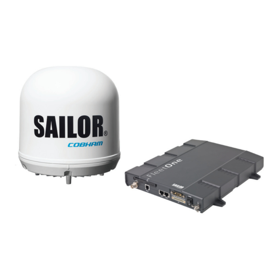
Optional: IP Handset SAILOR Fleet One antenna The SAILOR Fleet One system uses the SAILOR Fleet One antenna, which is a small size maritime 2-axis stabilized BGAN antenna. For information on how to install the antenna, see Chapter 2, Installation. -
Page 12: Tools For Setup And Use
The devices must be on the same LAN. If you have an IP Handset (minimum version 1.8) from Cobham SATCOM, it can be used for displaying status, accessing a subset of controls and views and entering the PIN code for the terminal. - Page 13 Chapter 1: Introduction Access to services and interfaces The following table shows which equipment and connectors you can use to access the services listed in the left column. Connector on terminal Service Phone LAN (PoE) Data Computer or WLAN access point Standard voice Analogue phone IP handset or...
-
Page 14: Chapter 2 Installation
Chapter 2 Installation This chapter describes how to install the SAILOR Fleet One antenna and the SAILOR Fleet One terminal. It has the following sections: • Unpack your SAILOR Fleet One • Mounting considerations for the antenna • Antenna mast design •... -
Page 15: Mounting Considerations For The Antenna
Chapter 2: Installation Mounting considerations for the antenna When looking for a place to mount the SAILOR Fleet One antenna, make the following considerations: • Do not place the antenna close to large objects that may block the signal. Place the antenna with free line of sight in all directions to ensure proper reception of the satellite signal. -
Page 16: Radiation Hazard
(below approximately 10 m) between radar antenna and the SAILOR Fleet One antenna. Therefore it is recommended to ensure as much vertical separation as possible when the SAILOR Fleet One antenna has to be placed close to a radar antenna. 98-141368-A... - Page 17 If the d min. separation listed below is applied, antenna damage is normally avoided. “d min.” is defined as the shortest distance between the radar antenna (in any position) and the surface of the SAILOR Fleet One antenna. X-band (~ 3 cm / 10 GHz) damage distance d min.
- Page 18 For optimum performance we recommend a minimum distance of 3 meters from the BGAN antenna to VSAT antennas. Auxiliary Terrestrial Component (ATC) The SAILOR Fleet One system is resilient to ATC base stations (future terrestrial mobile systems) that operate inside the Inmarsat band and that may be located near the coast. Other transmitters See Minimum distance to transmitters on page 112 in Appendix A for minimum recommended distance to transmitters in the frequency range below 1000 MHz.
-
Page 19: Antenna Mast Design
Antenna mast mounting Mast mount kit: The top of the SAILOR Fleet One antenna mast should be fitted with the dedicated mounting kit available from Cobham SATCOM. Assemble the mast mount kit according to the assembly instruction included with the kit. - Page 20 If this is not possible, provide extra deck plate propping. Antenna mast length The below table shows the values for a SAILOR Fleet One antenna mast without stays or wires. Note that these values are only guidelines - always consider the environment and characteristics of the ship before deciding on the mast dimensions.
-
Page 21: Install The Antenna
The maximum allowed RF-loss in the antenna cable is 20 dB at 1660 MHz. This is to ensure the performance of the system. Recommended antenna cables The table below shows recommended cable types and maximum cable lengths for SAILOR Fleet One. Absolute maximum Cable Type length... - Page 22 In some cases there will be condensation inside the radome. The gasket in the bottom centre of the SAILOR Fleet One antenna is designed to lead any water away from the radome. Make sure the drainage gasket is not blocked when you mount the antenna.
-
Page 23: Mount The Antenna
-60°, which is the maximum rotation angle (pitch and roll) for the SAILOR Fleet One antenna. Do not block the drainage hole in the centre bottom of the antenna. -
Page 24: Mounting Considerations For The Terminal
Chapter 2: Installation Mounting considerations for the terminal Where to place the terminal Temperature conditions The terminal must be placed in a ventilated area with free space around all sides of the unit, except the bottom side. Ambient temperature range is –25 °C to +55 °C. If the terminal is installed in a location where the ambient temperature may exceed 45 °C, we recommend placing the terminal where unintentional contact is avoided. -
Page 25: Install The Terminal
Chapter 2: Installation Install the terminal Ground the terminal Antenna cable The antenna ground is connected to the terminal ground by means of the coax cable with a TNC connector at both ends. For information on antenna grounding, see Ground the antenna on page 13. Ground stud To ensure that the terminal is grounded –... - Page 26 Chapter 2: Installation Ground connection through the mounting surface In addition to the ground stud you may connect the terminal chassis to ground through the mounting surface. Make sure you have a good electrical connection between the terminal chassis and the mounting surface. 1.
- Page 27 Chapter 2: Installation Mount the Basic cable support (optional) If you want to use a cable support for your terminal, you can acquire a Basic cable support (“Accessories kit F/ Terminal”, spare part no. S-673738A) from your distributor. When mounted on the terminal the Basic cable support offers a number of holders to which you can secure the cables from the terminal, using cable strips.
- Page 28 Chapter 2: Installation To install the terminal on a bulkhead Terminal with no cable support Do as follows to mount the terminal on a bulkhead: 1. Insert four screws through the mounting holes and into the mounting surface. This mounting method cannot be used for grounding. If you are using the Important mounting surface for grounding, you must use the threaded bushings on the underneath of the terminal instead.
-
Page 29: Connect Cables
Chapter 2: Installation Connect cables The connector panel The connector panel has the following connectors: DC power input Antenna Phone 2 x LAN Ground • 1 Antenna connector (TNC) • 1 Phone connector • 2 LAN connectors with Power over Ethernet (PoE) •... -
Page 30: Dc Power Input
Chapter 2: Installation Antenna interface on the terminal The antenna interface on the terminal connects to the SAILOR Fleet One antenna. The connector on the terminal is a TNC female connector. An antenna cable (10 m) is included in the delivery. - Page 31 Chapter 2: Installation Pinout The power connector is a Mixed D-Sub connector 7W2, control pin male/ power pin male. The below table shows the pinout for the connector and the colours of the corresponding wires. Colour of wire in Pin number Pin function power cable 5 4 3 Vin+...
- Page 32 Chapter 2: Installation To connect a remote on/off switch The terminal has a remote on/off function. When the terminal power switch is in the “on” position you can remote-control the power function. By installing a switch that can short-circuit the “Remote on/off” pins (2 and 5) in the power connector you can power the pin 5 terminal on or off with this remote switch.
- Page 33 Chapter 2: Installation Phone interface The terminal has one RJ-11 connector for connecting an analogue phone. Pinout The Phone connector is an RJ-11, 6/4 female connector. The table and figure below show the connector outline and pin assignments. RJ-11 female connector Pin number Pin function 1 2 3 4 5 6...
-
Page 34: Lan Interface
Chapter 2: Installation LAN interface The terminal has two Ethernet LAN ports with Power over Ethernet (PoE). The PoE standard for the Ethernet ports is IEEE 802.3af, and the connectors are RJ-45 connectors. Power over Ethernet (PoE) The LAN connectors have PoE, which means they can be used to supply power to connected equipment, e.g. - Page 35 To connect a wireless LAN access point The SAILOR Fleet One does not have a built-in wireless LAN (WLAN) access point. If you want to use WLAN to access the SAILOR Fleet One you must connect an external WLAN access point.
- Page 36 Chapter 2: Installation I/O interface The terminal has an I/O connector with 5 configurable inputs/outputs The connector is a WieCon Type 8513S connector. A matching connector is included in the delivery. Pinout The figure and table below show the connector outline and pin assignments. Pin number Default configuration WieCon Type 8513S connector Ringer output...
- Page 37 Chapter 2: Installation I/O pin functions Output pins 1,2 and 3: Passive Activated Terminal setting: Terminal Terminal Normally closed Passive Activated Terminal Terminal Terminal setting: Normally open Pin 1: Ringer output. Pin 1 acts as a built-in switch in the terminal. You can configure Pin 1 to be Normally closed or Normally open, using the web interface.
- Page 38 Chapter 2: Installation Pin 3: Indicator for data connection. Pin 3 can be used as an indicator for active data connections. You can configure pin 3 to Normally closed or Normally open. • Normally Closed: The internal switch at pin 3 is normally closed (pin 3 is connected to ground). When there is an active data connection, the switch opens (no connection to ground).
- Page 39 Chapter 2: Installation Input pin 5/8 (example): Ignition off Ignition on Terminal Terminal Terminal setting: Pin 8 Pin 8 Active high Pin 5 Pin 5 Ignition off Ignition on Terminal setting: Terminal Terminal Pin 8 Pin 8 Active low Pin 5 Pin 5 The functions of the I/O pins are as follows: Pin 5/8: Ignition input.
- Page 40 Max wire cross-section for stranded cable: 0.75 mm Pin connection: The switch and lamp connect to the I/O connector on the SAILOR Fleet One. The next sections describe how to connect. For details on the I/O pins, see the previous section.
- Page 41 Chapter 2: Installation To connect the data indicator lamp The data indicator lamp is used to show if there is an active data connection. Specifications for the lamp: • Colour: Orange • Operating voltage: 12 VDC • Operating current: 7/14 mA ±15% X1, Negative polarity X2, positive polarity The below procedure is an example with default configuration of I/O pins, and the lamp is...
-
Page 42: Power Cable Selection
Power cable selection A power cable of 1 m is supplied with the SAILOR Fleet One terminal. Use this cable if possible. If 1 m is not long enough, you can extend the cable according to the guidelines in this section. -
Page 43: Power Cable Recommendations
Chapter 2: Installation Power cable recommendations Overview The terminal is delivered with a power cable, which can be extended according to the recommendations in this section. • When extending the power cable, positive and negative supply wires must be installed closely together side by side to keep cable inductance low. - Page 44 Chapter 2: Installation To calculate the maximum cable extension, do as follows: 1. First measure the source impedance in the ship installation as shown in Measuring the ship source impedance on page 34. 2. Then find the resistance per meter for the cable type you are going to use. For 4 mm /AWG 11, the value is 4 mOhm/m at 20 °C For 1.5 mm...
-
Page 45: Chapter 3 Get Started
Start up the SAILOR Fleet One Insert the SIM card Note that the SAILOR Fleet One terminal requires a SIM card dedicated to the Fleet One service. The terminal can only access the BGAN network when the right type of SIM card is installed. -
Page 46: Ignition System
Using the built-in web interface of the terminal with an administrator password, you can apply a SIM PIN, so that you have to enter a PIN code to access the SAILOR Fleet One system and the BGAN satellite network. For details, see Configure the SIM PIN on page 80 If a PIN is required, you can enter the PIN using an analogue phone, an IP Handset or the web interface. -
Page 47: Connect A Smartphone
Connect a smartphone Wireless access point The SAILOR Fleet One does not have a built-in WLAN access point. If you want to use wireless devices with your SAILOR Fleet One you must connect an external WLAN access point to the LAN interface. - Page 48 Codec priority: Highest priority codec type: G.711 You must set up the user name and password in the web interface of the SAILOR Fleet One to match the IP handset settings. See Connecting and configuring IP handsets or smartphones on page 70.
-
Page 49: Connect An Ip Handset
To connect a 3rd party IP handset Connect the IP handset to LAN 1 on the SAILOR Fleet One terminal and set up the SIP server details in your IP handset and the terminal’s built-in web interface as described in Configuration for making calls on page 40. -
Page 50: Connect An Analogue Phone
For information on how to access the Internet, see Connect to the Internet on page 44. To connect through a wireless access point The SAILOR Fleet One does not have a built-in wireless LAN (WLAN) access point. If you want to use wireless devices with your SAILOR Fleet One you must connect an external WLAN access point to the LAN interface as described in Wireless access point on page 39. -
Page 51: Make A Call
870772420567, dial 00 870 772420567. If the SAILOR Fleet One number is listed in the web interface, you can look it up by selecting PHONE BOOK > Mobile numbers. See Phone number of the SAILOR Fleet One on page 58. -
Page 52: Connect To The Internet
192.168.0.1. 3. The built-in web interface of your SAILOR Fleet One terminal opens. With the web interface you can set up and control the SAILOR Fleet One and see status information. 4. At the top of the page, click the button Start data connection. -
Page 53: Chapter 4 Operation
Chapter 4 Operation This chapter describes the options for making calls and data connections using the SAILOR Fleet One. It has the following sections: • Phone calls • Data connection • The built-in web interface • Dashboard • Phone book •... - Page 54 If there was an error establishing the connection, refer to the Troubleshooting guide on page 126. If you have the IP Handset from Cobham SATCOM, the handset may show an error message. Depending on the type of error, the web interface may also show an error message. See Event list or Event log on page 98.
- Page 55 For further information, see Phone number of the SAILOR Fleet One on page 58. If the SAILOR Fleet One numbers are not available in the web interface, refer to the documents included with your airtime subscription. To make local phone calls You can make local calls between various phones connected to the terminal.
- Page 56 Chapter 4: Operation Dialling functions Local numbers and special-purpose numbers There are a number of dialling functions available in the terminal. The following list shows the allocated special-purpose numbers for the terminal. Number Function 0 * followed by # or off-hook key. Redial last called number on this interface.
-
Page 57: Data Connection
A user data connection for connecting your computer or other device to the Internet. • A connection for tracking your SAILOR Fleet One, that is for sending distance reports or interval reports from the SAILOR Fleet One to a tracking server. See Track the SAILOR Fleet One on page 87. - Page 58 3. The built-in web interface of your SAILOR Fleet One terminal opens. With the web interface you can set up and control the SAILOR Fleet One and see status. 4. At the top of the page, click the button Start data connection.
-
Page 59: The Built-In Web Interface
IP address of the terminal. The default IP address of the terminal is http://192.168.0.1. The web interface opens with the Dashboard, or, if the SAILOR Fleet One terminal is waiting for a PIN, it prompts you to enter the PIN (see SIM PIN on page 63.) - Page 60 Chapter 4: Operation Overview of the web interface Below is an overview of the web interface. Icon bar Contents section Signal strength Navigation pane • The navigation pane holds the main menu. Clicking an item in the menu opens a submenu in the navigation pane or a new page in the contents section.
- Page 61 Chapter 4: Operation To navigate the web interface To expand a menu, click the menu in the navigation pane. • To access status and settings, click the relevant subject in the navigation pane or click • the relevant icon in the icon bar. The status or settings are displayed in the contents section.
-
Page 62: Dashboard
Airtime provider. The name of your airtime provider. • GPS position. The GPS position of your SAILOR Fleet One System. • Status. The status of the SAILOR Fleet One System. The status can be one of the • following: Displayed text Meaning Scanning The terminal has instructed the antenna to scan for a BGAN signal. - Page 63 Chapter 4: Operation Displayed text Meaning Ready The terminal has registered and connected to the SAS and is ready to accept a service request (a call or a data session). Data active The terminal has established a call or a data session through the BGAN network.
- Page 64 Chapter 4: Operation To see information on calls and data connections The following sections in the Dashboard show information on calls and data sessions. The counters for calls and data sessions are only intended as a guide and cannot be Note used for direct comparison with your airtime bill.
-
Page 65: Phone Book
• Change, delete or add new names and phone numbers. If you are using an IP Handset from Cobham SATCOM with the terminal, the contacts Note from this terminal phone book are included (read only) in your handset phone book. - Page 66 At the bottom of the page, click Delete all entries in phone book. Phone number of the SAILOR Fleet One The phone number of your SAILOR Fleet One is not listed at delivery. The user must Note enter the number received from the airtime provider.
-
Page 67: Call Log
Chapter 4: Operation Call log If power to the system is interrupted, the information on the currently ongoing calls Note (connection time) and data sessions (transferred data) cannot be saved. This could mean that the airtime and bandwidth usage registered in the Call log will be inaccurate and there is a risk of being charged for more airtime than registered in the web interface. -
Page 68: Sms Messages
Chapter 4: Operation SMS messages To see new SMS messages When a new message has arrived, the icon bar at the top of the web interface shows an unopened envelope. Click the envelope to see the new message(s) or click MESSAGES from the left navigation pane. - Page 69 The message is now sent and moved to the Sent folder. To send an SMS message to the SAILOR Fleet One To send an SMS to the SAILOR Fleet One, dial + <SAILOR Fleet One phone number> Inbox, Outbox and Sent messages The Inbox contains incoming messages that have been read and moved from the •...
- Page 70 Chapter 4: Operation To configure message settings To set up the default message options You can set up general options for your outgoing messages. These settings apply by default to all your outgoing messages. Note, however, that you can change the Delivery notification setting for an individual message.
-
Page 71: Sim Pin
• Use an analogue phone connected to the terminal. • Use an IP Handset from Cobham SATCOM Using the web interface with an administrator user name and password you can Note change the PIN and enable or disable the use of a PIN. For further information, see... - Page 72 If you do not hear a “busy” or dialling tone, you may have entered a wrong PIN. See Wrong PIN below. To enter the PIN using the IP Handset from Cobham SATCOM With an IP Handset connected to the terminal, do as follows: 1.
- Page 73 Chapter 4: Operation 4. Enter the PIN. When the display shows the handset ready symbol in the upper right corner, the handset is ready for making a call. Wrong PIN After having entered the user name and password for the terminal you have 3 attempts to enter the SIM PIN, before you are asked to enter the PUK (Pin Unblocking Key).
-
Page 74: Chapter 5 Configuration
Chapter 5 Configuration This chapter describes how to configure the SAILOR Fleet One. using the web interface. It has the following sections: • Set up the data connection • Set up the interfaces • Select a preferred satellite • Log on as administrator •... -
Page 75: Set Up The Data Connection
However, you may still use the tracking function or an external data connection if enabled. See External data connections on page 85 or Track the SAILOR Fleet One on page 87. 3. At Automatic activation, select Enabled or Disabled. -
Page 76: Set Up The Interfaces
Chapter 5: Configuration Set up the interfaces To configure the LAN interface In the web interface you can set up the IP addressing between the terminal and devices connected to the terminal. The terminal has a built-in DHCP server, which is used to dynamically assign IP addresses to devices connected to the terminal. - Page 77 You may connect your IP handsets directly to the LAN interfaces or use a PoE switch to connect more handsets. You may also connect a smartphone via a WLAN access point connected to the LAN interface. The SAILOR Fleet One terminal supports connection of up to 4 handsets or smartphones through the LAN interface.
- Page 78 1. Connect the IP handset to one of the LAN ports of the terminal, or connect your smartphone to a WLAN access point connected to the LAN interface. If it is an IP Handset from Cobham SATCOM, the IP Handset starts up and is automatically registered and assigned the first available number.
- Page 79 The handset remains in the list after disconnecting. When the handset is connected again, it is automatically recognized and ready for use. For IP Handsets from Cobham SATCOM: When the terminal and the handset have recognized each other, a Configure link appears next to the IP Handset in the list. Click this link to access the built-in web interface of the IP Handset.
- Page 80 Chapter 5: Configuration To configure the I/O interface The terminal has an I/O connector with 5 configurable inputs/outputs. For details on their functions and how to connect, see I/O interface on page 28. To change the configuration of the I/O pins, do as follows: 1.
-
Page 81: Select A Preferred Satellite
The SAILOR Fleet One terminates all ongoing connections and deregisters from the current satellite before registering on the new satellite. If you have selected one of the satellites, your SAILOR Fleet One will only try to Note register on the selected satellite. This means that if the antenna is outside the coverage area for that satellite, the SAILOR Fleet One will not be able to register with the BGAN network. -
Page 82: Log On As Administrator
Chapter 5: Configuration Log on as administrator The settings under Administration are password protected. Once you have entered the administrator user name and password you have access to all settings. If you have not entered anything for 30 minutes, you are logged off automatically. To log on To log on, do as follows: 1. - Page 83 Chapter 5: Configuration The ADMINISTRATION page is now updated to let you change the user name and password, Save/load a configuration or log off. A number of subpages are now available under ADMINISTRATION. To reset the administrator password If you have forgotten the administrator password, do as follows: 1.
- Page 84 Chapter 5: Configuration 3. Type in the reset code obtained from your supplier and click Reset. 4. Type in the user name admin and the default password 1234. 5. Click Logon. 6. For information on how to change the password, see the next section To change the administrator password on page 76.
-
Page 85: Save Or Load A Configuration
Save or load a configuration To save the current configuration to a file If you need to reuse a configuration in another SAILOR Fleet One terminal, you can save your current configuration to a file, which can then be loaded into the other terminal. -
Page 86: Call Charges
Chapter 5: Configuration Call charges If you know the tariff for your subscribed services, you can enter these tariffs in the web interface and automatically calculate the charges for your calls and data sessions. To enter the call tariffs, do as follows: 1. -
Page 87: Log Handling
This will reset the Time connected counters on the Calls page. Data limits You can set a limit for the use of data services with the SAILOR Fleet One system by specifying a maximum number of MB for the data connection. -
Page 88: Configure The Sim Pin
If you have entered the call charges in the menu Call charges, the system automatically calculates and displays the maximum charges for your data sessions. Cobham SATCOM does not take responsibility for the correctness of the estimated Note charges. This calculation is only an estimate of the charge, based on the tariff entered by the user. - Page 89 Chapter 5: Configuration To change the PIN To change the PIN used to access the terminal, do as follows: 1. Select ADMINISTRATION > SIM PIN. 2. Under CHANGE PIN type in the Old PIN. 3. Type in the New PIN and retype it on the next line. 4.
-
Page 90: Set Up User Permissions
Change general settings means change the selection of satellite. Control connections from IP handsets means to start/stop data sessions using the IP Handset from Cobham SATCOM (master handset with the number 0501). 3. At ALLOW AT COMMANDS ON:, select • yes to allow the use of AT commands on the LAN interface, or •... -
Page 91: Restricted Dialling
Chapter 5: Configuration AT commands are low-level commands used to control modems, in this case the SAILOR Fleet One terminal. They are typically used during service and maintenance or when troubleshooting the terminal. 4. Click Apply. The settings to which access is denied are now greyed out for the non-administrator user. - Page 92 Chapter 5: Configuration The numbers or masks must be max. 32 digits and may start with +. No other special characters are allowed. A mask is the first part of a phone number, and it covers all numbers that start with that first part. See the example below. Mask Numbers accepted 00453955880...
-
Page 93: External Data Connections
Chapter 5: Configuration External data connections You can connect external devices e.g. for fishery reporting. These external devices communicate with the SAILOR Fleet One using PPPoE or AT commands through the LAN interface. Ext. data 1 Ext. data 2 You can have two external data connections. To set up the data connections, do as follows (the procedure is the same for Ext. - Page 94 Chapter 5: Configuration 2. Select Enabled to enable the use of this external data connection. If you select Disabled, this data connection cannot be used. 3. If you have installed a data connection switch, select Yes or No next to I/O control. •...
-
Page 95: Track The Sailor Fleet One
Chapter 5: Configuration Track the SAILOR Fleet One The SAILOR Fleet One system can be used for tracking purposes. You can set up the terminal to report to a server at certain time intervals or after moving a specified distance. - Page 96 3. Type in the Server IP address, Server port, Client port and Encryption key for your server connection. • IP address. The IP address of the server that the SAILOR Fleet One will report to. • Server port. Port number on the server. Default number is 7474.
-
Page 97: Antenna Rf Noise Filter
Chapter 5: Configuration Antenna RF noise filter The SAILOR Fleet One system has a built-in filter that makes it resilient to interference from terrestrial mobile systems that operate inside the Inmarsat band and that may be located near the coast. -
Page 98: Chapter 6 Maintenance And Troubleshooting
If this manual does not provide the remedies to solve your problem, you may want to contact your Airtime Provider or your local distributor. Lists of certified partners and distributors are available on www.cobham.com/SATCOM. Select Service and Support from the top menu bar and then AVIATOR, EXPLORER, SAILOR Service and Support. -
Page 99: Update Software
To upload software from your computer to the terminal, do as follows: 1. Download the new software as described in the next section, or acquire the software from Cobham SATCOM and save it on your computer. 2. Open the web interface and do one of the following: If the PIN has been accepted (or a PIN is not required), select SETTINGS >... - Page 100 Internet. Note that it can take several minutes to download the software. If you don’t want to use airtime you can acquire the software from Cobham SATCOM, save it on your computer and then connect the computer to the terminal.
-
Page 101: Part Numbers
After saving the software, follow the procedure in the previous section (To upload software from your computer) to upload the software from the computer to your terminal. Part numbers System units SAILOR Fleet One system Item Part number SAILOR Fleet One antenna 403050C-00581... -
Page 102: Troubleshooting Guide
Chapter 6: Maintenance and troubleshooting Troubleshooting guide The below table provides information on some of the problems that might occur, including possible causes and remedies to solve the problems. Problem Possible cause Remedy No signal or weak signal The view to the satellite is Make sure the antenna has a clear from the BGAN satellite. - Page 103 Chapter 6: Maintenance and troubleshooting Problem Possible cause Remedy A Phone connection The cable is not properly Connect the cable. cannot be established. connected. The cable type or For information on the correct type connector type is not of connector and cable, refer to correct.
-
Page 104: Status Signalling
Event messages. • Event log. Indicators, event messages and logs are described in the following sections. Power indicator The SAILOR Fleet One terminal has one LED indicator. Functions of the Power indicator. LED status Meaning Unit is off On, green... -
Page 105: Generate A Diagnostic Report
The diagnostic report contains relevant information for troubleshooting. When contacting your distributor for support, please enclose this file. To generate a diagnostic report, access the web interface of the SAILOR Fleet One and do as follows: 1. From the left navigation pane, select HELP DESK. -
Page 106: Event Messages
Chapter 6: Maintenance and troubleshooting Event messages Display of event messages The terminal can detect events during POST (Power On Self Test) or CM (Continuous Monitoring). When the terminal detects an event that requires your action, it issues an event message. - Page 107 Chapter 6: Maintenance and troubleshooting Explanation Remedy Event Text 00270 to Voice services cannot be Contact your distributor. Voice module 00279 accessed by the terminal error 00280 to The Ethernet interface on the Contact your distributor. Ethernet module 00289 terminal cannot be used. error 00300 to GPS module error The GPS module is out of...
- Page 108 The SAILOR Fleet One no Make sure the Satellite signal 01409 longer receives a signal from SAILOR Fleet One has a clear lost the satellite. view to the satellite. 01500 to SIM card missing No SIM card is detected in the Insert SIM card.
- Page 109 Chapter 6: Maintenance and troubleshooting Explanation Remedy Event Text 02900 to The SAILOR Fleet One does Restart the terminal. Network failed 02909 not accept the network as a authentication If the problem persists, contact valid BGAN network. your distributor. 03500 to...
- Page 110 Chapter 6: Maintenance and troubleshooting Explanation Remedy Event Text 08010 The input voltage has dropped Ensure a stable power supply to Undervoltage has below an acceptable level. The the terminal. been detected terminal will be shut down in 10 seconds if the situation persists.
- Page 111 Check that both the antenna Firmware image is not supported by the and the terminal are of the doesn't support terminal. type SAILOR Fleet One. antenna hardware Contact your distributor if the problem persists. 08034 New firmware was successfully Reboot the terminal. Contact...
- Page 112 Chapter 6: Maintenance and troubleshooting Explanation Remedy Event Text 0804B You are not using the right Only use the antenna(s) Illegal combination of antenna and intended for use with your combination of terminal. terminal. antenna and terminal 0804C The terminal is set up to use a Enter the web interface and The selected select SETTINGS >...
-
Page 113: Extended Status
Chapter 6: Maintenance and troubleshooting Extended status To see the Extended status page, select HELPDESK > Extended status. To see updated information on the Extended status page, click Refresh. The Extended Status page shows the following information: • The antenna Product ID (must always be TT-3050C-581). •... -
Page 114: Self Test
Chapter 6: Maintenance and troubleshooting Self test The Self test performs system test on the SAILOR Fleet One system, similar to the tests that are performed during the Power On Self Test (POST). The terminal must reboot to perform the self test. All ongoing calls or data Important sessions will be terminated. -
Page 115: Reset Button
Chapter 6: Maintenance and troubleshooting Reset button To access the Reset button The terminal has a Reset button placed next to the SIM slot behind the SIM cover. The functions of this button is described below. To press the Reset button, use a pointed device. Function of the Reset button The Reset button on the terminal has the following functions: Action... - Page 116 Chapter 6: Maintenance and troubleshooting Action Function For service use only! While the terminal is booting, press and hold the Reset The bootloader initiates software upload. This firmware button. upload procedure is only to be used if the other procedures fail due to missing or corrupted firmware.
-
Page 117: List Of Reserved Subnets
Chapter 6: Maintenance and troubleshooting List of reserved subnets Some IP subnets are reserved for internal use in the terminal. If any of these addresses are assigned to external equipment connected to the terminal, the terminal and connected equipment will not be able to communicate. The following local IP subnets are reserved for internal use in the terminal. -
Page 118: Sailor Fleet One Antenna
Appendix A Technical specifications SAILOR Fleet One antenna General specifications Item Specification Frequencies Inmarsat I-4 Transmit 1626.5 - 1660.5 MHz Receive 1525.0 - 1559.0 MHz Inmarsat Alphasat Extended L-Band (XL) Transmit 1626.5-1660.5 MHz and 1668.0-1675.0 MHz Receive 1518.0 - 1559.0 MHz Channel spacing 1.25 kHz... - Page 119 Appendix A: Technical specifications Environmental specifications Item Specification Water and dust IPX6 spray proof in all directions, no dust test. Ambient Operational: -25° to +55 °C Temperature Storage: -40° to +85 °C Operating humidity 100%, condensing Ice, survival Up to 25 mm of ice Wind load, max.
- Page 120 Heave: 0.7 g Turning rate: 36°/s; 12°/s Headway: 22 m/s (42 knots) Minimum distance to transmitters The table below shows the minimum recommended distance to transmitters in the frequency range below 1000 MHz. Recommended distance to SAILOR Fleet One antenna. 98-141368-A...
- Page 121 Appendix A: Technical specifications Outline, SAILOR Fleet One antenna Dimensions are in mm. 98-141368-A...
-
Page 122: Sailor Fleet One Terminal
Appendix A: Technical specifications SAILOR Fleet One terminal General specifications Item Specification Weight 2.2 kg (4.9 lbs) Dimensions 231 mm x 278 mm x 41 mm (9.1” x 10.9” x 1.6”) Global services Voice 4 kbps AMBE+2 Data Up to 100 kbps 2-wire telephone One connector: RJ-11 female. - Page 123 Appendix A: Technical specifications Item Specification Antenna interface One connector, TNC-female Inmarsat I-4 power: 1525 to 1559 MHz: -94 dBm to -64 dBm 1626.5 to 1660.5 MHz: -9 dBm to +11 dBm Inmarsat Alphasat power: 1518 to 1559 MHz: -94 dBm to -64 dBm 1626.5 to 1660.5 MHz and 1668.0 - 1675.0 MHz: -9 dBm to +11 dBm Power supply: 18-29 V DC...
- Page 124 Appendix A: Technical specifications Outline, SAILOR Fleet One terminal Connector panel, top view and end view. Dimensions are in mm. 98-141368-A...
- Page 125 Appendix A: Technical specifications Side view and bottom view. Dimensions are in mm. Weight: 2.2 kg. 98-141368-A...
-
Page 126: Glossary
Glossary Glossary Auxiliary Terrestrial Component. Hybrid satellite terrestrial systems that use terrestrial repeaters to combine the wide area coverage capabilities of geostationary or low earth orbit satellites with urban coverage and in building penetration provided from terrestrial networks. American Wire Gauge. A means of specifying wire diameters. BGAN Broadband Global Area Network. - Page 127 Glossary Global Positioning System. A system of satellites, computers, and receivers that is able to determine the latitude and longitude of a receiver on Earth by calculating the time difference for signals from different satellites to reach the receiver. Input/Output IAI-2 Inmarsat Air Interface-2.
- Page 128 Glossary POST Power On Self Test. A test sequence that runs every time the system is powered up or reset. Radio Frequency. Electromagnetic wave frequencies between about 3 kilohertz and about 300 gigahertz including the frequencies used for communications signals (radio, television, cell-phone and satellite transmissions) or radar signals.
-
Page 129: Index
Index Index calls IP handsets, enable or disable, 71 access to settings make or receive, 46 limit in web interface, 82 outgoing, received and missed, 59 administrator logon see in Dashboard, 56 web interface, 74 short dial, 58 administrator password using WLAN access point, 40 change, 76 charge for call, 78... - Page 130 Index distance to other transmitters, 112 Internet drainage of antenna, 14 connect to, 44 drawing IP addresses antenna, 113 reserved, 109 terminal, 116 IP handsets connect, 41 connect to LAN interface, 27 set up, 69 items included in delivery, 6 event messages, 98 events list of, 98...
- Page 131 116 in web interface, 57 phone number, 58 limited numbers, 83 terminal specifications, 114 phone number satellite of SAILOR Fleet One, 58 select, 73 satellite network change, 81 connect to, 39 enable or disable, 80 save configuration to file, 77...
- Page 132 Index technical specifications, 110 web interface temperature, 16 access, 51 terminal administrator logon, 74 cable support, 19 antenna properties, 105 grounding, 17 call charges, 78 installation location, 16 call log, 59 installing, 17 dashboard, 54 outline drawing, 116 data connection, 67 specifications, 114 description, 51 test...
Need help?
Do you have a question about the SAILOR Fleet One and is the answer not in the manual?
Questions and answers