
Summary of Contents for Alarmmate GSM Alarm System
-
Page 1: User Manual
A New User Friendly Concept GSM Alarm System for Your Assets! GSM Alarm System User Manual Ver 1.20 Date Issued: 2012-09-14 Website: Http://www.alarmmate.co.za Ver 1.00 Date Issued: 2012-09-01... -
Page 2: Table Of Contents
A Top Safety and Protection Solution Worldwide! Table of Contents Brief introduction -----------------------------------2 Safety Directions ------------------------------------2 Standard Packing list ------------------------------3 Physical Layout -------------------------------------3 Features -----------------------------------------------6 Settings -----------------------------------------------8 Operating Instructions --------------------------18 Installation -------------------------------------------21 Add wireless sensors ----------------------------26 Technical specifications ------------------------28 Important information ---------------------------29 Maintenance-----------------------------------------29 Quality Warranty -----------------------------------29 Trouble Shooting Guide-------------------------30... -
Page 3: Brief Introduction
Alarm System and influence it’s performance. Avoid Use at Gas Station Do not use the GSM Alarm System at a gas station. Power off the GSM Alarm System if it is near fuel or chemicals. Power it off near Blasting Places Please follow relevant restrictive regulations. -
Page 4: Standard Packing List
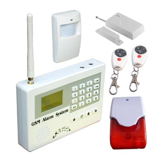
A Top Safety and Protection Solution Worldwide! Use Qualified Maintenance Service Maintenance can be carried out only by a qualified maintainer. Waterproofness The product is not waterproof. Please install it in dry places and keep it dry. 3. Standard Packing List Control Unit X1 Wireless Magnetic Door Sensor X1 Wireless Remote Controls X 2... - Page 5 A Top Safety and Protection Solution Worldwide! Interface 1 Description Power External Power Connector, Connect to 2A@12V DC power through AC/DC Adaptor. Siren Will start for 60seconds when alarm is triggered. The siren or strobe siren should be <12V DC. GSM ANT Connect the GSM ANT, if the GSM signal is not strong, then please change the 3dB GSM ANT.
- Page 6 A Top Safety and Protection Solution Worldwide! Ground point, connect to another wire of the wired Detector. Digital input 4, connect to one wire of the wired Detector. Digital input 5, connect to one wire of the wired Detector. Ground point, connect to another wire of the wired Detector. Digital input 6, connect to one wire of the wired Detector.
-
Page 7: Features
A Top Safety and Protection Solution Worldwide! 5. Features 5.1 The advantages of the GSM Alarm System Two-way Voice communication or wiretap is available; LCD displays the entire setup menu; Armed, Partial Armed (At house or Stay mode), Disarmed and SOS are available;... - Page 8 A Top Safety and Protection Solution Worldwide! 5.2 Functions & Features of the GSM Alarm System GSM Frequency: Dual-Band(900/1800MHz), Quad-Band is optional(850/900/1800/1900Mhz); Supports armed, Partial armed (At house or Stay mode) or disarmed, SOS by remote control or mainframe keyboard;...
-
Page 9: Settings
A Top Safety and Protection Solution Worldwide! 15) Supports internal speaker to the user to use as a two-way voice communication; 16) It is Compatible with PT2262 and PT2242 wireless IC; 17) Standby internal rechargeable battery which can last 18 hours; 18) Based on the GSM communication network and Operation Menu Display technology, the system can be applied to wide range situations. - Page 10 A Top Safety and Protection Solution Worldwide! Please note: if the income call is from the preset number (Includes SMS Alert number and Auto-dial numbers), then if answered before 6 tones, will create a two-way voice communication. After 6 tones, it will enter into a wiretap status.
- Page 11 A Top Safety and Protection Solution Worldwide! Alarm link output indicator, when alarmed, will turn on and last 4minutes, meaning the alarm link output relay is closing. : Separate output relay indicator, when the independent output relay is closed, the indicator will be on, when the independent output relay is opened, the indicator will be off.
- Page 12 A Top Safety and Protection Solution Worldwide! SOS, Panic Button. 6.2 Main Menu In standby mode, press the button, you will see the Menu. ---To check the settings and event records of the 1. View system ---To setup the system functions, requires password, 2.
- Page 13 A Top Safety and Protection Solution Worldwide! 6.2.2 Setup 1. Add/Del RF Parts ---To add or remove wireless sensors or remote controls and edit their attributes 2.Wired Zones Set ---To setup Wired Zone parameters of the system 3.Basic Setting ---To setup basic parameters of the system 4.
- Page 14 A Top Safety and Protection Solution Worldwide! Auto-Dial Tel. Numbers for 3 times one by one, and Send SMS to the Pre-set SMS Alert Numbers. In the meantime it will drive the siren for 60seconds and close the link-Output relay for 4 minutes. 2) After you enter the menu, the attribute of the zone will be displayed in the LCD, if this zone has been assigned a wireless sensor, it will display “V”.
- Page 15 A Top Safety and Protection Solution Worldwide! Intrusion from Living Room Normal Intrusion from Bed Room 1 Normal Intrusion from Bed Room 2 Normal Intrusion from Bed Room 3 Normal Intrusion from Front Balcony Normal Intrusion from Behind Balcony Normal Intrusion from 1F Window Normal Intrusion from 2F Window...
- Page 16 A Top Safety and Protection Solution Worldwide! 1) The Nodes Type NC,NO,EOL should reference the wired input sensor type. The Default is NC and all the inputs are shorted with wires. If you want to contact the wired sensors, then please replace the short wires by wired sensors directly.
- Page 17 A Top Safety and Protection Solution Worldwide! ---To setup the SMS Alert Number, must be cell 1.SMS Phone No. phone numbers, total 3. ---To setup the Auto-dial telephone number, total 2. Auto-dial Tel No. is 5 numbers. ---To setup the time and date information. The 3.
- Page 18 A Top Safety and Protection Solution Worldwide! For example: In South Africa, the country code is 0027, please note, do not write +27. The user cell phone number is for example 082 123 4567 and has been assigned as a SMS Alert number, the SIM Card number in the panel is for example 082 321 7654. Problem 1: Alarm but the user hasn’t received the SMS Alert.
- Page 19 A Top Safety and Protection Solution Worldwide! ---To setup the starting time to arm and the Ending 1.Edit Timer time to disarm. ---To setup the starting and ending time to work. 2. Watchdog Timer ---To setup the remote control operation report 3.
-
Page 20: Operating Instructions
A Top Safety and Protection Solution Worldwide! table. If the setup is successful, the system will return OK to confirm the operation. E.g.: Modify the first wireless zone name as Front Door Opened by Intruder! You should edit a SMS Content: 1234#M01# Front Door Opened by Intruder!# ,the 1234 is the password. - Page 21 A Top Safety and Protection Solution Worldwide! the siren will stop and you can listen in on the alarm area by phone. Press the button “ ” on the remote control, or press Disarm button on the Keyboard then input the password, the Control Unit disarms immediately. ICON will be off.
- Page 22 A Top Safety and Protection Solution Worldwide! xxxxBB Example “xxxx” stands for the password 1111BB (1-4 digits). Return SMS When the Password is 1111 System deactivated. 7.2.3 Switch On the independent output relay Example xxxxCC “xxxx” stands for the password 1111CC (1-4 digits).
-
Page 23: Installation
A Top Safety and Protection Solution Worldwide! status. It is not the alarm link Output Relay Status. 8. Installation Before installing the control unit, sensors and sirens, please help to test the system firstly, including wireless sensor, power supply, GSM signal, etc. Please ensure the wireless sensors and electrical appliances are more than 3~5m from the mainframe. - Page 24 A Top Safety and Protection Solution Worldwide! Wireless glass break sensor can also be used (see below) For a scrolling steel door, a special wireless scroll steel door magnetic sensor must be used due to interference of the wireless signal caused by the steel door.
- Page 25 A Top Safety and Protection Solution Worldwide! Wireless curtain sensor, detection area illustration below: 8.4 Install the Wired Sensors and Electricity equipments Please see below wiring diagram, then fix the related wired sensors and the sensors connected to the related digital inputs. Tips! 1) Please setup the NC, NO, EOL type in the PC Programmer correctly;...
- Page 26 A Top Safety and Protection Solution Worldwide! series with every input, if you don’t connect the sensor to the input, please connect a 2.2K resistor in series to instead. Moreover, only the digital detector, NC type, can be used in EOL mode. Please see the below diagram. 4) If you setup the input type as NO, then please keep the two points of the inputs free and the sensor type must be NO.
-
Page 27: Add Wireless Sensors
A Top Safety and Protection Solution Worldwide! 8.5 Install the Control Unit In order to avoid destruction of the control unit by intruders, please install it in a concealed location, convenient to the operator. If applicable, ensure that an uninterruptible AC power outlet is available near the Control Unit. - Page 28 A Top Safety and Protection Solution Worldwide! Notice: 1. Some wireless sensors must be coded by manual as below 9.1 step; some wireless sensors don’t need manual coding, because it will use the learning code sensor. Follow step 9.1 for learning the code wireless sensor, it is the same as the PIR-100B and DM-100A.
-
Page 29: Technical Specifications
A Top Safety and Protection Solution Worldwide! Select the Zone number, press Ok, to finish press OK, select the Normal Type Or Stay Type, then following the instruction: 1.Turn On the Device, means trigger the RF sensor, the system will show a code, then press Enter Key on the keyboard. -
Page 30: Important Information
A Top Safety and Protection Solution Worldwide! Rated Voltage: 9~12VDC 2A Standby current: 30-40mA Siren Output Voltage: 12VDC Working temperature: -10℃~+60℃; Storage temperature:-20℃~+60℃ Relative humidity: 10-90%, No condensation Work frequency: 900/1800 MHz or 850/900/1800/1900MHz Communication protocol: GSM PHASE 2/2+ (include data service) Wireless sensor receiving frequency: 433 MHz Wireless sensor permission quantity:... -
Page 31: Maintenance
A Top Safety and Protection Solution Worldwide! 12. Maintenance 1) If the Control Unit works, but the remote control and other sensors fail, please check and change the battery. 2) If the remote control works, but the Control Unit fails to send SMS texts, switch the power of Control Unit off and switch it on after one minute. - Page 32 LOCK and correct format. after send Numbers. 4) Also, please change another GSM 3) Caps Lock letters in operator SIMCard to test it. command the SMS Commands. Website: www.alarmmate.co.za Email: alarmmate@gmail.com Tel: 0832673842 0110427167 Page 31 of 32 Ver 1.0...
Need help?
Do you have a question about the GSM Alarm System and is the answer not in the manual?
Questions and answers