Advertisement
Quick Links
Advertisement

Summary of Contents for Wellav SMP260
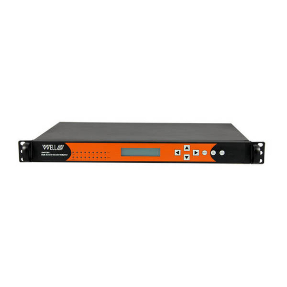
- Page 1 Digital Encoder & Transcoder Quick Installation Guide...
-
Page 2: Installation Instruction
SMP Encoder & Transcoder Quick Installation Guide V1.0-N 1. Installation Instruction Mounting unit to a 19” rack When selecting the installation site, try to comply with the following: Protective Ground - The protective ground lead of the building's electrical installation should comply with national and local requirements. -
Page 3: Wiring Connection
SMP Encoder & Transcoder Quick Installation Guide V1.0-N PIC-1.1-2 Wiring Connection Before setting up the connection, please turn off the equipment and all other connected external devices. The equipment and all connected external devices are required grounded. Turn on the devices only after the wiring connection is completed. Otherwise the device may be damaged. -
Page 4: Power Connection
SMP Encoder & Transcoder Quick Installation Guide V1.0-N Set up cable connection for output signal: either through ASI (area 3) or TS/IP (area 4) Set up connection for network management control: shown in area 5. In order to ensure a smooth communication between the management PC and the equipment, please separate the connection of management port and TS/IP output port to different switch. -
Page 5: Network Connection Setup
SMP Encoder & Transcoder Quick Installation Guide V1.0-N 2. Operation Instructions Powering Up & Initializations Before powering-up the device, make sure that all cables are correctly connected (refer to chapter 1.2). The device is correctly connected to the power inlet and grounded. - Page 6 PC’s s. The IP and the server’s IP should be in the same section. Step 3: reboot the device to take effect. Step 4: ping the new IP on PC to check whether the SMP260 can connect to the management PC. 2.2.3 Configuration through NMS Accessing the equipment through NMS can be very convenient for remote configuration of the equipment.
- Page 7 SMP Encoder & Transcoder Quick Installation Guide V1.0-N Copy the NMS program on the CD to any folder of the management PC; Use mouse to double click the NMS icon and run the NMS program. First Time Log On For first time log on, User Name and Password are required.
- Page 8 SMP Encoder & Transcoder Quick Installation Guide V1.0-N Pic-2.2-2 The interface can be divided into four areas according to its functionality. (1) Toolbar. It includes shortcut to change password and save setting etc. (2) Equipment list. If more than a piece of equipment is connected to the NMS, the equipment will be listed in this area by its IP address.
- Page 9 SMP Encoder & Transcoder Quick Installation Guide V1.0-N ① Different colors of histogram indicate different meaning: Orange: the total input bit rate; Blue: the effective input bit rate; Yellow: the total output bit rate; Green: the effective output bit rate; Red: alarm indicator, it means the actual output bit rate (it’s proportional to the amount of the programs you transfer from input port to output port in ‘Program Info’) is more than the output bit rate of some channel you set in sub-board.
- Page 10 SMP Encoder & Transcoder Quick Installation Guide V1.0-N Pic-2.3-1 For encoding module quick setup, following are the key parameters that need to change to meet with the application need: Parameters Description Select a channel to configure its parameters. Settings work separately for each channel. The Channel whole page setup will take effect only to the corresponding channel.
- Page 11 SMP Encoder & Transcoder Quick Installation Guide V1.0-N the max encode rate and the mix encode rate in CBR mode. Audio Encode Rate To choose the encoding bitrate for the audio. Audio Mode To select the audio mode To select correct frame rate according to the input Frame Rate source.
- Page 12 SMP Encoder & Transcoder Quick Installation Guide V1.0-N Pic-2.3-2 Parameters Description In this ‘ChannelSelect’, user can select a channel to configure its ChannelSelect parameters. On: enable the IP receiving function. Enable Off: disable the IP receiving function. Note: this parameter setting applies to all channels. Channel configuration EnableChannel Enable or disable corresponding input channel...
- Page 13 SMP Encoder & Transcoder Quick Installation Guide V1.0-N The bigger values it is, the stronger capabilities it has to correct FEC Parameter the data mistakes. But the FECL and FECD should be less than 100. IP module-Output The “Output” setting menu is to set the IP output function for transmitting multicast/unicast IP stream.
- Page 14 SMP Encoder & Transcoder Quick Installation Guide V1.0-N DestIPAddress Set IP address of the multicast/unicast. Protocol Select UDP/RTP for multicast/unicast EncapNumTSPackets Rang 1~7. (Num 7 is recommended) 2.3.3 Program IN/OUT configuration in “Program Info” tab Operation Buttons Transfer button: to transfer the selected stream/PID from the input program window to the output program window.
- Page 15 SMP Encoder & Transcoder Quick Installation Guide V1.0-N Pic-2.3-4 ① Input Program Configuration: The “Input Program Configuration” is on the left side of the “Program Info” window. It displays all the inserted modules information and the received input streams. SD‐Encoder CVBS Slot1 ...
- Page 16 SMP Encoder & Transcoder Quick Installation Guide V1.0-N Board1~4 represents the corresponding slots of the equipment. If the slot is inserted with a card module, the corresponding Board No. will be displayed on the “Input Program Configuration” window, and the name of the inserted module will be displayed after the Board No.
- Page 17 SMP Encoder & Transcoder Quick Installation Guide V1.0-N Scan completes and receives data Pic-2.3-6 Output program configuration Select the port which you want to transmit the output stream. Pic-2.3-7 Select a TS stream, click the mouse right button. In the pop-up menu, select “Add TS”.
- Page 18 SMP Encoder & Transcoder Quick Installation Guide V1.0-N Pic-2.3-8 Input the “Original Network ID” and “TS ID” for the channel, and click the “Add” button. Pic-2.3-9 The input “Original Network ID” and “TS ID” will be assigned to the selected output TS (channel).
- Page 19 SMP Encoder & Transcoder Quick Installation Guide V1.0-N button on the TS, and select “Delete”. Pic-2.3-12 Select TS which is going to be transmitted on the left hand side “Input Program Info” window, and select the port, TS (channel) which are going to carry the transmission on the right hand side “Output Program Info”...
- Page 20 SMP Encoder & Transcoder Quick Installation Guide V1.0-N Pic-2.3-14 Follow above operation steps, user can set the selected input stream to be transmitted at any assigned output TS (channel). Note: This Quick Installation Guide only contains tutorials with simple instructions for device installation and configuration.
Need help?
Do you have a question about the SMP260 and is the answer not in the manual?
Questions and answers