
Subscribe to Our Youtube Channel
Related Manuals for Kelvinator R-404A


Summary of Contents for Kelvinator R-404A
- Page 1 National Refrigeration Products SERVICE & INSTALLATION MANUAL DIPPING CABINETS R-404A Refrigerant 51-1298-02...
- Page 2 If additional information is necessary, call the factory. Our toll free number is 1-800-486-8369. Technical assistance engineers are willing to assist you in any way possible. Office hours are from 8:00 a.m. to 5:00 p.m., Eastern Standard Time. Important information is contained in this manual which should be retained in a convenient location for future reference.
- Page 3 Introduction...
-
Page 4: Introduction
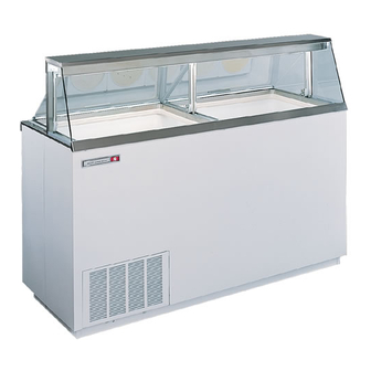
These Dipping Cabinets are designed to merchandise ice cream or yogurt type products. Dipping cabinets are produced in four sizes: 4, 8, 12, and 16 facings of ice cream containers. The cabinet systems contain R-404A refrigerant, metered into the system by a capillary tube. The evaporator is a cold wall which has the refrigerant lines strapped to the inner liner of the cabinet. -
Page 5: Table Of Contents
TABLE OF CONTENTS INTRODUCTION Condenser Fan Motor Replacement ........44 Ballast Replacement ............45 Introduction ................ 2 Metering Device / Heat Exchanger Replacement ....46 Table of Contents ..............3 Cabinet Troubleshooting Guide ........47 CABINET SPECIFICATIONS/DIMENSIONAL DRAWINGS Compressor Troubleshooting Guide ........ 49 4HR &... -
Page 6: Cabinet Specifications/Dimensional Drawings 4Hr & 4 Hc & Export
Compressor Size 1/4 Hp. Shipping Weight (App.) 235 lbs. Condenser Type Bare Tube Evaporator Type Cold Wall Refrigerant R-404A Refrigerant Control Capillary Tube Defrost System Manual Rated Amps Electrical Specs. 115V, 60 Hz., 1 Ph. 220V, 50 Hz., 1Ph 220V, 60 Hz., 1 Ph. -
Page 7: 8Hr & 8Hc & Export
Compressor Size 1/3 Hp. Shipping Weight (App.) 365 lbs. Condenser Type Bare Tube Evaporator Type Cold Wall Refrigerant R-404A Refrigerant Control Capillary Tube Defrost System Manual Rated Amps Electrical Specs. 115V, 60 Hz., 1 Ph. 220V, 50 Hz., 1 Ph. -
Page 8: 12Hr & 12Hc & Export
3/4 Hp. 3/4 Hp. Shipping Weight (App.) 525 lbs. Condenser Type Bare Tube Evaporator Type Cold Wall Refrigerant R-404A Refrigerant Control Capillary Tube Defrost System Manual Rated Amps Electrical Specs. 115V., 60 Hz, 1 Ph. 220V, 50 Hz, 1 Ph. -
Page 9: 16Hr & 16Hc & Export
3/4 Hp. 3/4 Hp. Shipping Weight (App.) 525 lbs. Condenser Type Bare Tube Evaporator Type Cold Wall Refrigerant R-404A Refrigerant Control Capillary Tube Defrost System Manual Rated Amps Electrical Specs. 115V, 60 Hz., 1 Ph. 220V, 50 Hz, 1 Ph. -
Page 10: Handling & Installation
HANDLING & INSTALLATION-Illuminated Dipping Cabinets FREIGHT DAMAGES AND SHORTAGES UNCRATING THE CABINET The cabinet should be moved as close as possible to IMPORTANT the operating location before removing the skid. Be The cabinet was inspected and packaged at the sure to follow the steps in the “INSPECTING FOR factory, and should have arrived in excellent DAMAGES”... -
Page 11: Grounding Instructions
B. Check for traces of oil on the compressor pan which IMPORTANT could mean a broken or leaking refrigeration line. UNDER NO CIRCUMSTANCE SHOULD THE Do not, under any circumstance, cut or remove the COMPRESSOR BE STARTED WHEN OIL IS round grounding plug from the appliance plug. -
Page 12: Product Load Line Location
PRODUCT LOAD LINE LOCATION 7" BELOW BREAKER KEEP PRODUCT BELOW RED LINE NOTE: KEEP PRODUCT BELOW THIS LINE. INTRODUCTION... -
Page 13: Principles Of Operation
SECTION II Principles of Operation... -
Page 15: General Operations Information
GENERAL OPERATIONS All the dipping cabinet models are of the same basic Compressors being used in these cabinets utilize design, consisting of a bare tube condenser and a cap refrigerant 404A and polyol ester oil. Because of the tube fed tank wrap evaporator. hygroscopic nature of this oil, extreme care must be taken when any component is changed within the Ice formation on the walls over a period of time is... -
Page 16: 4Hr & 4Hc Electrical & Refrigeration Specs
Manufacturer: G.E. Fan Blade Width of Blades: 1 7/8" Lamp F20T12 CW REFRIGERATION - Refrig. Charge: R-404A / 11.5 oz. / 326.02 grams / No. 4 Stat Position AMBIENT TEMPERATURE 70°F / 21.1°C 80°F / 27°C 90°F / 32.5°C CONTROL SETTINGS #4 C.S. -
Page 17: 8Hr & 8Hc Electrical & Refrigeration Specs
Fluorescent Manufacturer: G.E. Lamp F20T12 CW (STD) F17T8 / SP35 (3500K) REFRIGERATION - Refrig. Charge: R-404A / 17 oz. / 481.95 grams / No. 4 Stat Position AMBIENT TEMPERATURE 70°F / 21.1°C 80°F / 27°C 90°F / 32.5°C CONTROL SETTINGS #4 C.S. -
Page 18: 12Hr & 12Hc Electrical & Refrigeration Specs
Width of Blades: 1 29/32" Fluorescent Manufacturer: G.E. Lamp F40T12CW (STD) F32T8/SP35 (3500K) REFRIGERATION - Refrig. Charge: R-404A / 25 oz. / 708.75 grams / No. 4 Stat Position AMBIENT TEMPERATURE 70°F / 21.1°C 80°F / 27°C 90°F / 32.5°C CONTROL SETTINGS #4 C.S. -
Page 19: 16Hr & 16Hc Electrical & Refrigeration Specs
Fan Blade Width of Blades: 1 29/32" Lamp F40T12CW (STD) F32T8/SP35 (3500K) REFRIGERATION - Refrig. Charge: R-404A / 27 oz. / 765.45 grams / No. 4 Stat Position AMBIENT TEMPERATURE 70°F / 21.1°C 80°F / 27°C 90°F / 32.5°C CONTROL SETTINGS #4 C.S. -
Page 20: E4Hr & E4Hc Electrical & Refrigeration Specs
Diameter: 8" # of Blades: 3 Lamp F20T12/CW Fan Blade Width of Blades: 1 7/8" REFRIGERATION - Refrig. Charge: R-404A / 11.5 oz. / 326.02 grams / No. 4 Stat Position AMBIENT TEMPERATURE 70°F / 21.1°C 80°F / 27°C 90°F / 32.5°C CONTROL SETTINGS #4 C.S. -
Page 21: E8Hr & E8Hc Electrical & Refrigeration Specs
Manufacturer: G.E. Fan Blade Width of Blades: 1 7/8" Lamp F20T12/CW REFRIGERATION - Refrig. Charge: R-404A / 17 oz. / 481.95 grams / No. 4 Stat Position AMBIENT TEMPERATURE 70°F / 21.1°C 80°F / 27°C 90°F / 32.5°C CONTROL SETTINGS #4 C.S. -
Page 22: E12Hr & E12Hc Electrical & Refrigeration Specs
" Lamp F40T12CW Pressure Switch C.O.: 350# C.I.: 250# REFRIGERATION - Refrig. Charge: R-404A / 25 oz. / 708.75 grams / No. 4 Stat Position AMBIENT TEMPERATURE 70°F / 21.1°C 80°F / 27°C 90°F / 32.5°C CAVITY TEMPERATURE 2°F / -17°C 4°F / -16°C... -
Page 23: E16Hr & E16Hc Electrical & Refrigeration Specs
Width of Blades: 1- ⁄ " Lamp F40T12CW REFRIGERATION - Refrig. Charge: R-404A / 27 oz. / 765.45 grams / No. 4 Stat Position AMBIENT TEMPERATURE 70°F / 21.1°C 80°F / 27°C 90°F / 32.5°C CAVITY TEMPERATURE 2°F / -17°C 4°F / -16°C... -
Page 24: Wiring Diagram
WIRING DIAGRAM - 4HR, 4HC / 8HR, 8HC E4HR, E4HC / E8HR, E8HC E4HR2, E4HC2 / E8HR2, E8HC2 PRINCIPLES OF OPERATION... -
Page 25: 12Hr, 12Hc / 16Hr, 16Hc Wiring Diagram
WIRING DIAGRAM - 12HR, 12HC / 16HR, 16HC PRINCIPLES OF OPERATION... -
Page 26: E12Hc2, E12Hr2 / E16Hc2, E16Hr2
WIRING DIAGRAM - ECKDC67, EKDC67 / ECKDC87, EKDC87 E12HC2, E12HR2 / E16HC2, E16HR2 PRINCIPLES OF OPERATION... -
Page 27: Wiring Diagram
WIRING DIAGRAM - 8HC, 12HC, 16HC WITH 3500K LIGHTS PRINCIPLES OF OPERATION... -
Page 29: Maintenance & Repair
SECTION III Maintenance & Repair... - Page 30 WARNING: To avoid the possibility of an electrical shock, turn OFF thermostat and unplug the power cord of the cabinet before cleaning or touching electrical connections or parts.
-
Page 31: Pre-Service Check List
MAINTENANCE & REPAIR — PRE-SERVICE CHECK LIST You may avoid the cost and inconvenience of an CUSTOMER COMPLAINT unnecessary service call by first reviewing this check OR STORED PRODUCT list of the most frequently encountered situations that 1. Check cleaning solutions used inside cabinet. are not the result of system component failure. -
Page 32: General Maintenance Information
SECTION III MAINTENANCE & REPAIR TOOLS: 8) Was the warm-up fast, as in three to six hours, or over a prolonged time, as in three to five days? To provide full service diagnostics and repairs on these cabinets the following tools are needed: 9) If the cabinet was running for a long time, was the temperature recovery after entering the cabinet A Volt Meter... - Page 33 ENTERING THE SYSTEM Use this time to check any joints for potential leaks. Entering the system should only be done as a last CHARGING resort. Extreme care must be used no matter what the reason is for entering the system. Of course there are You should use a charging cylinder to measure in the times it cannot be avoided, such as component or the correct amount of refrigerant.
-
Page 34: Compressor Installation / Diagnostics
COMPRESSOR INSTALLATION & MAINTENANCE / DIAGNOSTICS HOLD DOWN BOLTS CAUTION All models with Copeland compressors have hold This type valve should be tightly capped except when down bolts. The compressor has a metal hold down making the gauge connection. band strapping it tightly to the cabinet body. This band TO CHECK FOR OPEN WINDINGS should be removed and discarded upon installation. - Page 35 COMPRESSOR INSTALLATION & MAINTENANCE / DIAGNOSTICS TO CHECK CAPACITORS 1. Disconnect the cabinet from the power supply. 2. Make sure the capacitors are discharged before checking. (Shunt across the terminal of capacitor with a heavy insulated wire.) 3. Remove the wires from the capacitors. 4.
-
Page 36: Cleaning & Maintenance
CLEANING & MAINTENANCE CLEANING THE CABINET EXTERIOR 5. Wash the can skirts and the entire interior storage area with warm water and baking soda solution — Wipe the exterior occasionally with a cloth dampened about a tablespoon of baking soda per quart of in mild detergent water;... -
Page 37: Cleaning The Lid & Touch-Up Painting
CLEANING THE LID If the lid has been removed from the cabinet, wash with plenty of non-abrasive soap or detergent and water. Use the bare hand to feel and dislodge any caked soil. Rinse thoroughly with clean water. Do not use hard, rough cloths that will scratch the surface of the plastic lid. -
Page 38: Lid Seal Replacement
LID SEAL REPLACEMENT from epics The lid seal is located on the server side of the cabinet, attached to the underside of the stainless steel top. 1. Remove lids from the cabinet. 5. Replace the lid seal with new correct art number. Seal needs to be cut to fit the cabinet width. -
Page 39: Lid Gasket Replacement
LID GASKET REPLACEMENT 1. Remove the lid from the cabinet. 2. Set the lid on a flat, protected surface. 3. Rotate lid upside down. 4. Slide old gasket from the aluminum lid frame. 5. Install new gasket in the groove provided. -
Page 40: Lid Pivot Bushing Assembly Replacement
LID PIVOT BUSHING ASSEMBLY REPLACEMENT New Style Old Style The pivot pin bushing is located on the outside edge of Remove lid from cabinet. Lay the lid on a each lid. smooth, non-scratch surface. Simply unsnap lid pivot assembly and replace with a new part. -
Page 41: Center/End Pivot Rod Replacement
CENTER/END PIVOT ROD REPLACEMENT Remove lids from the cabinet. Remove 2 mounting screws from the mounting bracket. Replace the pivot bracket with correct new part number. Reinstall lid assembly. The 4-hole and 8-hole dipping cabinets have end pivot pins only. The 12- and 16-hole dipping cabinets have end and center pivot brackets. -
Page 42: Fluorescent Lamp Holder/Light Starter Socket Replac
FLUORESCENT LAMP HOLDER/LIGHT STARTER SOCKET REPLACEMENT The lamp holder and the light starter socket are located on the lamp channel assembly. 1. Disconnect the power to the cabinet. 2. Remove the lids from the cabinet. 3. Remove the fluorescent bulbs. 4. -
Page 43: Fluorescent Bulb & Starter Replacement
FLUORESCENT BULB & STARTER REPLACEMENT BULB STARTER REPLACEMENT (The fluorescent bulb starter is located on the lamp channel assembly. One starter is necessary per BULB REPLACEMENT bulb.) 1. Turn light switch off on the cabinet. 1. Turn light switch off on the cabinet. 2. -
Page 44: Thermostat Replacement
THERMOSTAT REPLACEMENT The thermostat is located on the server side of the cabinet, directly behind the service grill. It functions to control the temperature inside the cabinet. The range on the thermostat dial is adjustable from 1 to 7 (7 being the coldest setting). The OFF position is provided for defrosting the cabinet. -
Page 45: Master Power Supply Switch / Light Switch Removal
MASTER POWER SUPPLY SWITCH / LIGHT SWITCH REPLACEMENT The master supply switch (A) and the light switch (B) are located behind the grill panel, on the righthand server side of the unit. 1. Disconnect the power to the cabinet. 2. Remove the grill. 3. -
Page 46: Condenser Fan Motor Replacement
CONDENSER FAN MOTOR REPLACEMENT The condenser fan motor is located in the machinery compartment, directly behind the condenser coil. Motor Specifications: 220 Volts 60 Hz. 1 Phase 9 Watt 1. Disconnect the power to the cabinet. 2. Remove the grill panel. 3. -
Page 47: Ballast Replacement
BALLAST REPLACEMENT The ballast is located in the machinery compartment inside the electrical box. 1. Disconnect the power to the cabinet. 2. Remove the front grill. 3. Remove the electrical wiring box. 4. Disconnect the leads to the ballast. 5. Replace the ballast with correct part. 6. -
Page 48: Metering Device/Heat Exchanger Replacement
METERING DEVICE/HEAT EXCHANGER REPLACEMENT 1. Disconnect power to the cabinet. 7. Connect the end of the capillary on the new heat exchanger to the evaporator inlet tube. 2. Pull out the condensing unit. 8. Connect the suction line to the compressor valve 3. -
Page 49: Cabinet Troubleshooting Guide
CABINET TROUBLESHOOTING GUIDE TROUBLE COMMON CAUSE REMEDY UNIT WILL NOT RUN. Blown Fuse. Replace fuse. Check outlet with voltmeter, should check 115V plus or minus 10%. If circuit overloaded, either reduce load or have electrician install separate circuit. If unable to remedy any other way, install autotransformer. - Page 50 CABINET TROUBLESHOOTING GUIDE TROUBLE COMMON CAUSE REMEDY UNIT RUNS ALL THE TIME. Not enough air circulation around cabinet or Relocate cabinet or provide proper air circulation is restricted. clearances around cabinet. Poor lid seal. Check and make necessary adjustments. Refrigerant charge. Undercharge or overcharge--check, evacuate and recharge with proper charge.
-
Page 51: Compressor Troubleshooting Guide
COMPRESSOR TROUBLESHOOTING GUIDE PROBLEMS & CAUSE REMEDY Compressor won’t start—no hum. 1. Open line circuit. 1. Check wiring, fuses, receptacle. 2. Protector open. 2. Wait for reset - check current. 3. Control contacts open. 3. Check control; check pressures. Compressor won’t start—hums intermittently (cycling on protector). 1. -
Page 52: Fluorescent Lamp Troubleshooting Guide
FLUORESCENT LAMPS - TROUBLESHOOTING GUIDE Carrier Refrigeration uses standard fluorescent lamps in all of its applications. Standard one- and two- lamp ballast circuits are used. Replacement lamps should be purchased over the counter from a local electrical wholesaler. The table below indicates general problems that may be encountered with fluorescent lighting applications, possible causes, and corrective maintenance suggestions. - Page 53 TROUBLE COMMON CAUSE REMEDY NO STARTING EFFORT OR Open lamp cathode circuit due to broken If open, circuit is shown by continuity test cathode, air leak, or open weld. or by viewing end of bulb against a SLOW STARTING. pinhole of light. Replace lamp. Wrong lamp type used.
-
Page 54: Measurements - Starting Lamp Voltage
MEASUREMENTS - Starting Lamp Voltage TYPICAL TWO-LAMP RS BALLAST Starting Voltage TYPICAL TWO-LAMP RS BALLAST WHITE BLACK BALLAST The largest percentage of light ballast used today are of the two-lamp rapid start type. In order to read starting or open circuit voltage, as it is often called, remove both lamps from their sockets. -
Page 55: Parts Listing
PARTS LISTING With Illustration Identification... -
Page 56: Cabinet Parts - Exploded View
CABINET PARTS - EXPLODED VIEW CABINET PARTS - EXPLODED VIEW... -
Page 57: Cabinet Parts List
CABINET PARTS MODEL NO. MODEL NO. MODEL NO. MODEL NO. MODEL NO. MODEL NO. MODEL NO. MODEL NO. MODEL NO. MODEL NO. MODEL NO. Dipping Cabinets 12HC 12HC 16HC 16HC 12HR 16HR Curved & Flat & Export (3500K) (3500K) (3500K) PART NUMBER DESCRIPTION QTY GR.# QTY GR.# QTY GR.# QTY GR.# QTY GR.# QTY GR.# QTY GR.# QTY GR.# QTY GR.# QTY GR.# QTY GR.#... -
Page 58: Canopy Parts - Exploded View
CANOPY PARTS - EXPLODED VIEW CANOPY PARTS - EXPLODED VIEW... -
Page 59: Canopy Parts List
CANOPY PARTS MODEL NO. MODEL NO. MODEL NO. MODEL NO. MODEL NO. MODEL NO. MODEL NO. MODEL NO. MODEL NO. MODEL NO. MODEL NO. Dipping Cabinets 12HC 12HC 16HC 16HC 12HR 16HR Curved & Flat & Export (3500K) (3500K) (3500K) PART NUMBER DESCRIPTION U/M QTY GR.# QTY GR.# QTY GR.# QTY GR.# QTY GR.# QTY GR.# QTY GR.# QTY GR.# QTY GR.# QTY GR.# QTY GR.#... -
Page 60: Condensing Unit Exploded View
CONDENSING UNIT EXPLODED VIEW CONDENSING UNIT EXPLODED VIEW... -
Page 61: Condensing Unit Parts List
CONDENSING UNIT PARTS MODEL NO. MODEL NO. E4HC E8HC ECKDC-67 ECKDC-87 Dipping Cabinets 12HC 16HC E4HC2 E8HC2 E12HC2 E16HC2 Curved & Flat & Export 12HR 16HR E4HR E8HR EKDC-67 EKDC-87 E4HR2 E8HR2 E12HR2 E16HR2 PART NUMBER DESCRIPTION U/M QTY GR.# QTY GR.# QTY GR.# QTY GR.# QTY GR.# GR.# GR.#... -
Page 62: Electrical Components - Exploded View
ELECTRICAL PARTS - EXPLODED VIEW ELECTRICAL PARTS EXPLODED VIEW... -
Page 63: Electrical Components Parts List
ELECTRICAL PARTS MODEL NO. MODEL NO. MODEL NO. MODEL NO. MODEL NO. MODEL NO. MODEL NO. MODEL NO. MODEL NO. MODEL NO. MODEL NO. MODEL NO. Dipping Cabinets 12HC 12HC 16HC 16HC E4HC E8HC ECKDC-67 ECHKD-87 E4HC2 E8HC2 E12HC2 E16HC2 Curved &... -
Page 64: Lid - Exploded View
LID - EXPLODED VIEW LID - EXPLODED VIEW... -
Page 65: Lid Parts List
LID PARTS LIST LID PARTS MODEL NO. MODEL NO. MODEL NO. MODEL NO. Dipping Cabinets 12HC 16HC Curved & Flat & Export 12HR 16HR PART NUMBER DESCRIPTION QTY GR.# QTY GR.# QTY GR.# QTY GR.# 10-1141-* Lid, Plexiglas 08-0517-* Lid Frame, Top 23-0164-00 U-Clip 08-0520-*... -
Page 67: Accessories
ACCESSORIES... -
Page 69: Can Skirt Accessory Parts List
CAN SKIRT ACCESSORY PARTS LIST Can Skirt Assembly w/ Gripper ....50-3326-02 Gripper ............09-0202-00 Can Skirt Only ........10-0952-02 Thumbscrew ..........22-1729-00 Can Rack ..........15-0296-00 Support Bracket (Short) ......01-0930-00 Support Bracket (Long) ......01-0931-00 Thumbscrew ..........22-1729-00 Product Spacer ........05-1011-00 Product Spacer Angle ...... -
Page 70: Can Skirt Installation
CAN SKIRT INSTALLATION INFORMATION ACCESSORY PART NUMBER CABINET MODEL NUMBER 52-1804-01 4-Hole CKDC27, CKDC27C, DL4C 4HC & 4HR 52-1804-02 8-Hole CKDC47, CKDC47C, DL8C 8HC & 8HR (1) 52-1804-01 plus (1) 52-1804-2 12-Hole CKDC67, CKDC67C, DL12C 12HC & 12 HR (2) 52-1804-01 plus (1) 52-1804-2 16-Hole CKDC87, CKDC87C, DL16C 16HC &... - Page 71 CAN SKIRT INSTALLATION INFORMATION 11. Place product spacer E into the cabinet at center of tank. Eight-hole and 12-hole assemblies have one spacer bar; 16-hole has 2 spacer bars. 12. Can skirt is now installed. ACCESSORIES...
-
Page 72: Dipperwell Installation
DIPPERWELL INSTALLATION INFORMATION - 7300000 NOTE: There are provisions for either righthand or lefthand dipperwell positioning. To install dipperwell: 1. Remove plastic hole tabs. 2. Mount dipperwell to cabinet using (2) 1/4-20 x 1/2 M.S. 3. Mounting plate must be under flange of stainless steel cap. -
Page 73: Sanitary Base Leg Installation
ADJUSTABLE LEG KIT - 52-1831-01 ACCESSORIES... -
Page 74: Caster Installation
CASTER KIT- 52-1830-01 ACCESSORIES... -
Page 75: Lid Lock Kit Installation
INSTALLATION INSTRUCTIONS FOR LID LOCK KIT-52-2081-00 (DIPPING CABINETS) 1. Locate and drill a 5/16" (.313) dia. hole 3/8" (.375) from the edge of the handle. 2. Slip the hooked end of the lock bracket under the stainless steel top (see end view above), pull out to allow lid handle to pass and place the padlock through the handle and the bracket. -
Page 76: Can Clamp Installation
CAN CLAMP INSTALLATION ACCESSORIES... -
Page 77: Round Can Clamp Installation
INSTALLATION INSTRUCTIONS - ACCESSORY PART NO. 52-1874-01 ROUND CAN CLAMP - 9 Ú " to 9 Ú " Dia. - PLASTIC CANS Each accessory contains parts to clamp one 4-can 5. If it is necessary to increase clamping pressure, cluster of ice cream containers. install plastic shim or shims. -
Page 78: Half-Way Shelf Bottom Support Kit Installation
HALF-WAY SHELF BOTTOM SUPPORT KIT 1. Assemble vertical supports to cabinet with thumbscrews through top hole of support onto rivnuts in liner. The dimple formed in each support should be towards the wall. The four (4) short supports go over the unit compartment. 2. - Page 80 National Refrigeration Products 563 Corbin Road • Honea Path, South Carolina • (800) 486-8369...
Need help?
Do you have a question about the R-404A and is the answer not in the manual?
Questions and answers