Table of Contents
Advertisement
Quick Links
Advertisement
Table of Contents

Summary of Contents for HellasSAT Newtec Point&Play
- Page 1 Newtec Point&Play™ Setup Manual Version 1.2 - May 2008...
-
Page 3: Table Of Contents
Contents Contents Introduction ..............4 About this guide................4 Safety precautions................ 5 Material provided in the box............7 Material you need to provide yourself ..........9 Installation overview ..............10 Setting up the antenna ..........11 Step 1 - Choosing a suitable location ........... 12 Step 2 - Mounting the antenna pole.......... - Page 4 HELLAS SAT Point&Play Manual - page 3 Version 1.2 - May 2008...
-
Page 5: Introduction
Introduction 1 Introduction About this guide This guide provides a step-by-step procedure to install the HELLAS SAT terminal (consisting of the antenna and the IPmodem). Before installing Before starting to install the antenna, it is important to read the following sections: - Safety precautions (page 5) - Material provided in the box (page 7) - Material you need to provide yourself (page 9) -
Page 6: Safety Precautions
Do not use adapter plugs or remove the grounding prong from the plug. - Do not use the in-line power supply power cord when damaged in any form. HELLASSAT Point&Play Setup Manual - page 5 Version 1.2 - May 2008... - Page 7 Introduction Cautions A caution refers to an action or situation that could result in equipment damage or destruction if you do not follow the instructions. IPmodem - Always use the in-line power supply with the IPmodem. Using a different power supply may cause equipment damage.
-
Page 8: Material Provided In The Box
Introduction Material provided in the box 50 mm 20 mm 16 mm 8 mm 6 mm HELLASSAT Point&Play Setup Manual - page 7 Version 1.2 - May 2008... - Page 9 Introduction Material provided in the box: list Number on figure Item Quantity Masthead Brackets Pole clamps iLNB clamp iLNB (Interactive Low Noise Block downconverter) Screw 50 mm M6 Screw 20 mm M6 Screw 16 mm M6 Hex key F-connectors Parker Screw Feed arm Satellite dish Nut M8...
-
Page 10: Material You Need To Provide Yourself
- Minimum diameter: 40 mm. - Maximum diameter: 70 mm. - The antenna pole needs to be grounded according to local regulations. Consult with a licensed electrician if in any doubt. HELLASSAT Point&Play Setup Manual - page 9 Version 1.2 - May 2008... -
Page 11: Installation Overview
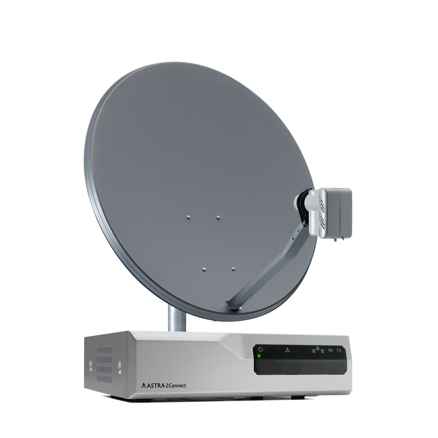
Introduction Installation overview The image below shows the results of a typical installation as described in the following pages. Please read these pages carefully to perform the installation. Satellite Power supply with adapter iLNB IPmodem Antenna Rx cable Tx cable Ethernet cable Version 1.2 - May 2008 HELLAS SAT Point&Play Setup Manual - page 10... -
Page 12: Setting Up The Antenna
Step 2 - Mounting the antenna pole (page 13) Step 3 - Mounting the antenna (page 14) Step 4 - Fixing the antenna cabling (page 21) Step 5 - Pointing the antenna (page 29) HELLASSAT Point&Play Setup Manual - page 11 Version 1.2 - May 2008... -
Page 13: Step 1 - Choosing A Suitable Location
Setting up the antenna Step 1 - Choosing a suitable location Outdoors: antenna - When setting up the antenna base, take account of the orientation the antenna must have. Orientation data are available in the Antenna Pointing Information document. - The antenna needs a clear view towards the satellite (without any buildings, trees... that may hinder the signal). -
Page 14: Step 2 - Mounting The Antenna Pole
Setting up the antenna Step 2 - Mounting the antenna pole When fixing the antenna pole on the base, use a spirit level to make sure the antenna pole stands upright. HELLASSAT Point&Play Setup Manual - page 13 Version 1.2 - May 2008... -
Page 15: Masthead
Setting up the antenna Step 3 - Mounting the antenna Insert the 2 brackets in the masthead (as shown). Use the 2 pole clamps and nuts to attach the masthead to the pole. - If the pole is low enough, you can first assemble the masthead, brackets and clamps and slide the assembly over the antenna pole. - Page 16 - Make sure the masthead is already pointing in the general direction of the satellite. To do so, use the pointing data available in the Antenna Pointing Information document. - Make sure to attach the masthead upright to the pole. HELLASSAT Point&Play Setup Manual - page 15 Version 1.2 - May 2008...
- Page 17 Setting up the antenna Attach the dish to the masthead with the appropriate screws and nuts. Version 1.2 - May 2008 HELLAS SAT Point&Play Setup Manual - page 16...
- Page 18 Setting up the antenna Insert the feed arm in the cut-away at the bottom of the dish and fix the arm with the appropriate bolts. HELLASSAT Point&Play Setup Manual - page 17 Version 1.2 - May 2008...
- Page 19 Setting up the antenna Attach the clamp around the iLNB using the appropriate nut and bolt. Do not to attach the clamp too tightly as you will need to adjust it later on. Version 1.2 - May 2008 HELLAS SAT Point&Play Setup Manual - page 18...
-
Page 20: Ilnb Clamp
Setting up the antenna Slide and click the iLNB clamp into the feed arm. HELLASSAT Point&Play Setup Manual - page 19 Version 1.2 - May 2008... - Page 21 Setting up the antenna The antenna is mounted. The result should look like the figure below. Version 1.2 - May 2008 HELLAS SAT Point&Play Setup Manual - page 20...
-
Page 22: Step 4 - Fixing The Antenna Cabling
- Grounding the iLNB (page 24) - Adjusting iLNB polarisation (page 25) - Connecting the iLNB to the IPmodem (page 27) - Connecting the IPmodem to your computer (page 28) HELLASSAT Point&Play Setup Manual - page 21 Version 1.2 - May 2008... - Page 23 Setting up the antenna Connecting the F-connectors on the coax cable You will need a cutter (and possibly pliers) to connect the F-connectors. To connect an F- connector to a cable: For the outdoor end of the cable, first slide the rubber boots over the coax cable. outside use Strip the coax cable as shown below.
- Page 24 Setting up the antenna Screw the F-connector to the wire by hand. 0,4cm Repeat this procedure for all 4 F-connectors. HELLASSAT Point&Play Setup Manual - page 23 Version 1.2 - May 2008...
- Page 25 Setting up the antenna Grounding the iLNB As you will use the antenna for internet access, you need to ground the antenna. To do so, you need a grounding wire (for grounding wire specifications, see page 9) and a bolt fitting the grounding connection on the masthead.
- Page 26 Check the scaling on the iLNB. Depending on the type of iLNB you have, the scaling of the iLNB may range: - from 0 to 180° - from -35 to +35° iLNB side view angle marker feed scale polarization scale HELLASSAT Point&Play Setup Manual - page 25 Version 1.2 - May 2008...
- Page 27 Setting up the antenna In the Antenna Pointing Information document, look up the value that applies to the city closest to your position. Set the iLNB to the angle you have found in the document. Lock the iLNB in the clamp with the securing bolt available on the iLNB. Version 1.2 - May 2008 HELLAS SAT Point&Play Setup Manual - page 26...
-
Page 28: Ilnb (Interactive Low Noise Block Downconverter)
Put the indoor TX and RX connectors in the appropriate TX and RX jacks on the IPmodem. Use an 11 mm spanner to screw the connectors on the IPmodem. DC 15V iLNB iLNB RESET HELLASSAT Point&Play Setup Manual - page 27 Version 1.2 - May 2008... - Page 29 Setting up the antenna Connecting the IPmodem to your computer Plug the network cable in the IPmodem’s and your computer’s ethernet ports. You can use the network cable provided in the box or a cable of your choice. Use the power adapter provided in the box to connect the IPmodem to a wall outlet. The result should look like the figure below.
-
Page 30: Step 5 - Pointing The Antenna
- Confirming antenna pointing in the software (page 44) Warning Do not stand in front of the iLNB or the antenna dish during pointing. Keep the space between the iLNB and the antenna dish clear. HELLASSAT Point&Play Setup Manual - page 29 Version 1.2 - May 2008... - Page 31 Setting up the antenna Setting the IPmodem software to pointing mode Before you start The procedure below assumes: - that your computer is DHCP enabled; - that you will connect a single computer to the IPmodem. If this is not the case or if you have another configuration, you will find more information in the Termincal User manual on the cd, in Appendixes Local Network Configuration and Changing your IP settings.
- Page 32 You can now start pointing the antenna. Note Whenever you redo the pointing procedure and access the IPmodem software, the button will be labelled Restart Pointing instead of Start pointing. HELLASSAT Point&Play Setup Manual - page 31 Version 1.2 - May 2008...
- Page 33 Setting up the antenna Using the Point&Play™ Tool The Point&Play™ Tool will help you point the antenna correctly. During the pointing procedure, the Point&Play™ Tool can produce various sounds, each having a specific meaning described below. You will thus need to put on the headphone whenever needed during the pointing procedure. Ensure that the volume of the Point&Play™...
- Page 34 Connect the headphone to the appropriate port of the Point&Play™ Tool. Make sure the Point&Play™ Tool is turned on and the volume is high enough. DC 15V iLNB iLNB RESET HELLASSAT Point&Play Setup Manual - page 33 Version 1.2 - May 2008...
-
Page 35: Important Notes
Setting up the antenna Rough pointing: vertical (elevation) Important notes - The procedures relating to rough horizontal and vertical pointing are described below in a sequential way. In reality, you will have to perform these two procedures simultaneously. - Whenever the procedure tells you to loosen a securing bolt or nut, slacken it just enough to allow the corresponding element to move freely. - Page 36 You can now remove the hex key from the eccentric E. Secure bolts (1) and (2). It is recommended not to secure the eccentric E (as you may damage it by doing so). HELLASSAT Point&Play Setup Manual - page 35 Version 1.2 - May 2008...
- Page 37 Setting up the antenna Rough pointing: horizontal (azimuth) To start horizontal pointing: Loosen the lock bolts (1) and (2) of the eccentric A (3). Rotate the eccentric (3) with the hex key until the letters A on the eccentric and the masthead point towards each other, as shown in the figure above.
- Page 38 As soon as you hear this continuous high pitch tone, secure the bracket nuts (4). It is recommended not to secure the eccentric A (as you may damage it by doing so). HELLASSAT Point&Play Setup Manual - page 37 Version 1.2 - May 2008...
- Page 39 Setting up the antenna Persistent low pitch If you keep hearing a low pitch tone, this might indicate one of the following issues: - Check if you have a clear line of sight, and no building, tree or other obstruction is blocking the path between the antenna and the satellite.
- Page 40 You then need to fine-point the antenna. Important note The procedures relating to vertical and horizontal fine-pointing are described below in a sequential way. In reality, you will have to perform these procedures simultaneously. HELLASSAT Point&Play Setup Manual - page 39 Version 1.2 - May 2008...
- Page 41 Setting up the antenna Fine-pointing: vertical Loosen bolt (1). Rotate the eccentric (3) until the Point&Play™ Tool produces a continuous high pitch tone. Secure bolt (1). Place the cap (4) on bolt (2) and secure it with the appropriate nut. Version 1.2 - May 2008 HELLAS SAT Point&Play Setup Manual - page 40...
- Page 42 Loosen the horizontal lock bolt (1) and (2). Rotate the eccentric (3) until the Point&Play™ Tool produces a continuous high pitch tone. Secure the horizontal lock bolts (1) and (2). HELLASSAT Point&Play Setup Manual - page 41 Version 1.2 - May 2008...
-
Page 43: Troubleshooting
Setting up the antenna Checking the antenna pointing Perform the following checks to make sure the antenna will resist external movements (wind...): Make sure all bolts are tightly secured. Shortly place your hand between the iLNB and the dish. As soon as you remove your hand, you should hear the continuous high pitch tone again. - Page 44 Slide the rubber boots over the connectors. Use tie-wraps to attach the cables to the feed arm. Make sure to leave some slack on the cables. The result should look like the figure below. HELLASSAT Point&Play Setup Manual - page 43 Version 1.2 - May 2008...
-
Page 45: Ipmodem
Setting up the antenna Confirming antenna pointing in the software Back to your computer, in the status page of the IPmodem, click the Pointing Completed button. You are now ready to surf the internet. Version 1.2 - May 2008 HELLAS SAT Point&Play Setup Manual - page 44...
Need help?
Do you have a question about the Newtec Point&Play and is the answer not in the manual?
Questions and answers