Table of Contents
Advertisement
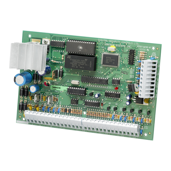
The PC4820 is a versatile Dual Card Reader Access Control
module which will enable you to meet the most
demanding access control requirements of an installation.
The PC4820 is monitored and programmed via the
PC4010/4020 control panel. Up to 16 PC4820 modules can
be connected to a PC4010/4020 via a 4-conductor Combus,
using standard, unshielded station wire.
Each PC4820 is capable of providing supervision for two
door inputs which may to assigned to any PC4010/4020
zone. Each door contact may be configured for any zone
end of line option which the control panel can provide.
Each of the two PC4820 Access Card Readers can be
programmed to function independently on different
doors, or together controlling access for both sides of one
door.
Control of the access points can be performed using a
variety of equipment. The PC4820 supports four different
types of card readers: the Polaris magnetic strip reader,
the Shadow Prox proximity card reader, the HID proximity
readers, and 26-bit standard Wiegand card readers. The
PC4820 also supports the use of any request to exit device
including the T-REX exit detector.
1.1 PC4820 Access Control Module
Specifications
Two Zone Inputs
• Two programmable supervised zones ( EOL resistors
– value )
• Zones may be programmed as Standard or Auxiliary
delay zone types
• PC4010/4020: up to 16 PC4820 can be added (up to
32 access points)
Non Volatile RAM (internal memory)
• Does not lose any system programming when the
module is powered down.
Introduction
S
e
c
t
i
o
n
1
Low Current Outputs
• Six low current outputs (open collector outputs
switched to ground 25mA max.) :
• Two LED terminals - To the LED input of the
reader
• Two BUZ terminals - To the Buzzer input of the
reader
• Two OUT terminals - Reserved for future use
Regulated Power Supply ( 1.5 Amp max. )
• Electronic shutdown protection of the battery,
auxiliary output, 5 and 12 V reader power supplies,
and lock device power output
• Auxiliary output supply: 12V
• LK1 and LK2 Door Strike power: 12V
• Reader Power 5V
• Reader Power 12V
Reader Technology
• Polaris, Shadow Prox, HID Proximity and 26-bit
Standard Weigand format
Access Card Compatibility
• Polaris POL-C1CN - Polaris Magnetic Cards
• Shadow Prox, Module Numbers:
SH-C1 - Shadow Prox Card
SH-K1 - Shadow Prox Keytag
• HID Proximity:
HID-C1325KSF - Proximity Card
HID-C134KSP - Proximity Keytag
• Weigand - Standard 26 bit formats
Battery
• 12V
7.0Ah recommended rechargeable gel-cell
DC
Transformer
• 16.5 V
, 40VA
AC
Operating Temperature
• 2
°
C to 40
°
C (35
°
Range
• 90
°
non-condensing humidity
Output Voltage
• Output voltage = 13.8V
fully charged battery). Devices that require power
from the PC4820 should be capable of operation over
the voltage range of 10 to 14V
• 5V Power Supply - Devices connected to the 5V
supply should be capable of operation between 4 and
6V.
, 125mA Max
DC
, 250mA Max
DC
, 125mA Max
DC
, 125mA Max
DC
F to 110
°
F) operational Temperature
(with normal AC and a
DC
.
DC
1
Advertisement
Table of Contents

Summary of Contents for DSC PC4820
-
Page 1: Introduction
• Polaris, Shadow Prox, HID Proximity and 26-bit readers, and 26-bit standard Wiegand card readers. The Standard Weigand format PC4820 also supports the use of any request to exit device Access Card Compatibility including the T-REX exit detector. • Polaris POL-C1CN - Polaris Magnetic Cards 1.1 PC4820 Access Control Module... -
Page 2: Installation And Wiring
PC4010/4020 v3.0 Installation Manual Instructions for details on wiring and proper (Section 2.4 “Capacitance Limits”). mounting locations.) NOTE: Do not run the Combus to the PC4820 in shielded 2 Tamper protection cable. A tamper switch may be installed on the cabinet to protect it from unauthorized entry. -
Page 3: Outputs - Led, Buz And Out Terminals
Access card readers with integrated keypads may be used When using this output to switch an external device, the with the PC4820. In order to use this reader type, the negative terminal of the device must be connected to the user must first present their access card. -
Page 4: Pc4820 Connection Chart
Can be used for Arm or Post inputs. See PC4820 Wiring Diagram for wiring instructions. * Tamper connection not available on the MiniProx detector PC4820 List of Supported Readers and Cards Reader Type Reader Part Numbers Supply Voltage Card Part Numbers... -
Page 5: Cabling Specifications
I n s t a l l a t i o n a n d W i r i n g PC4820 Access Control Module Reader Connections Polaris Readers (POL-1, POL-2, POL-2KP) Shadow Prox Readers * NOTE: Only use the +5V power supply when using NOTE: Only use the +12V power supply when using the Polaris Readers. -
Page 6: Programming The Pc4820
6. a downloading session has disconnected. If disabled, the LED on the access card reader will The data transfer can take up to 2.5 minutes per PC4820 not indicate the armed status. (Default = Yes) module. When the transfer is completed, all keypads will •... -
Page 7: Arming And Disarming With Access Cards
Zone 17 to 128 may be used (Zone 9 to 64 on 3.3 Arming and Disarming with Access Cards the PC4010). The PC4820 can be set up so that users may arm and You can use any zone supervision option provided by disarm, or postpone the autoarm of any active partition the PC4010/4020 for PC4820 zones. - Page 8 The default date schedule is 01. opened. The user must then enter their access code at a keypad to disarm the partition(s). Door Unlock Schedule NOTE: To disarm a partition or enter a partition which Ref # [0011XX01YY06] where XX = module #, YY = door # is armed, the user must be assigned to the partition, This schedule will determine when an access door will and the user’s disarm attribute must be enabled in...
-
Page 9: Access Level
3.8 Programming Access Cards one or more partitions. In order for an access card to function on the PC4820 the The default date schedule is 00 (disabled). card must first be programmed into the PC4010/4020. -
Page 10: Diagnostics
PC4820 is capable of providing diagnostics INPUTS DOOR 1) and AUX+. information for various conditions that may appear on 4. On the selected PC4820, connect a short from the the module. terminals marked as OUT (for OUT DOOR 1) and •... -
Page 11: Pc4820 Programming Worksheet
PC4820 Programming Worksheet Record your PC4820 module programming information here. Make one copy of this sheet for each PC4820 you will install. NOTE: XX = module #; YY = door # [0011] PC4820 Options [0011XX] PC4820 Module Number: I ___ _ _ _ I _ _ _ _ _ _ I... - Page 12 Security Products ©1998 Digital Security Controls Ltd. 1645 Flint Road, Downsview, Ontario, Canada M3J 2J6 (416) 665-8460 • Fax (416) 665-7498 • 1-800-387-3630 Printed in Canada 29002622 R0...
- Page 13 PC4820 v1.2 • Installation Manual WARNING: This manual contains information on limitations regarding product use and function and information on the limitations as to liability of the manufacturer. The entire manual should be carefully read.
-
Page 14: Limited Warranty
Installer’s Lockout Telephone Lines Any products returned to DSC which have the Installer’s Lockout option enabled and If telephone lines are used to transmit alarms, they may be out of service or busy for certain periods of time. Also an intruder may cut the telephone line or defeat its operation by more sophisticated means exhibit no other problems will be subject to a service charge. -
Page 15: Table Of Contents
2.5 Door Locking Devices – LK1 & LK2 Terminals ........................3 2.6 Access Card Readers ................................3 PC4820 Connection Chart ................................4 PC4820 List of Supported Readers and Cards ..........................4 Cabling Specifications ..................................5 PC4820 Access Control Module Reader Connections ........................ 5 Programming the PC4820 3.1 Programming Reader Types .............................. -
Page 16: Pc4820 Access Control Module Wiring Diagram
PC4820 Access Control Module • Lock device and Reader Connections • Battery and AC Connections • Typical Zone Circuits • Combus Connections...
Need help?
Do you have a question about the PC4820 and is the answer not in the manual?
Questions and answers