Table of Contents
Advertisement
Quick Links
Advertisement
Table of Contents

Subscribe to Our Youtube Channel
Related Manuals for Ross CrossOver 16

Summary of Contents for Ross CrossOver 16
- Page 1 Ross Video Limited CrossOver 16 Operator’s Manual Software Issue: 4.0...
- Page 2 The material in this manual is furnished for informational use only. It is subject to change without notice and should not be construed as commitment by Ross Video Limited. Ross Video Limited assumes no responsibility or liability for errors or inaccuracies that may appear in this manual.
- Page 3 Warning Hazardous Voltages — This symbol is intended to alert the user to the presence of uninsulated “dangerous voltage” within the product enclosure that may be of sufficient magnitude to constitute a risk of shock to persons. ESD Susceptibility — This symbol is used to alert the user that an electrical or electronic device or assembly is susceptible to damage from an ESD event.
- Page 4 Notice — Changes or modifications to this equipment not expressly approved by Ross Video Limited could void the user’s authority to operate this equipment.
- Page 5 Warranty and Repair Policy Ross Video Limited (Ross) warrants its switchers and related options, to be free from defects under normal use and service for a period of ONE YEAR from the date of shipment. Fader handle assemblies are warranted for the life of the product.
- Page 6 Company Address Ross Video Limited Ross Video Incorporated 8 John Street P.O. Box 880 Iroquois, Ontario, K0E 1K0 Ogdensburg, New York Canada USA 13669-0880 General Business Office: (+1) 613 • 652 • 4886 Fax: (+1) 613 • 652 • 4425 Technical Support: (+1) 613 •...
-
Page 7: Table Of Contents
Contents Introduction Advanced Operation About This Manual ..........1-1 Transition Limit..........4-1 Documentation Terms........1-1 Modifying Wipes..........4-1 Technical Support ..........1-1 Modifying DVE Transitions.......4-2 Switcher Installation .......... 1-1 Advanced Keying ..........4-3 Control Panel Overview........1-2 Aux Buses............4-5 Control Panel Rear Connections Overview ..1-3 Creating an FTP Connection ......4-6 Frame Overview.......... - Page 8 Copy Logs to USB ..........8-1 Calibration ............8-1 Diagnostics ............8-1 Error Messages ...........8-3 Specifications Dimensions............9-1 Weight: ...............9-1 Power Requirements ..........9-1 Ports..............9-1 Video Formats ............9-1 Inputs/Outputs ............9-1 GVG Editor Input Mapping .......9-2 GVG100 Protocol Supported Commands ..9-2...
- Page 9 What’s New The following features are new or have been updated in this software version: Setting Analog Output Reference Color Framing ................2-5 Background Double-Press ........................2-15 Media Transitions ..........................3-3 UltraChrome Chroma Key........................3-5 Accessing Aux Buses..........................4-5 Custom Controls ........................... 5-1 Memory Attributes..........................
-
Page 11: Introduction
Documentation Terms are available to react to any problem and to do whatever is necessary to ensure customer • “Switcher” refers to the CrossOver 16 switcher. satisfaction. • “Operator,” “User,” and “You” refer to the • Technical Support: (+1) 613-652-4886 person who uses the switcher. -
Page 12: Control Panel Overview
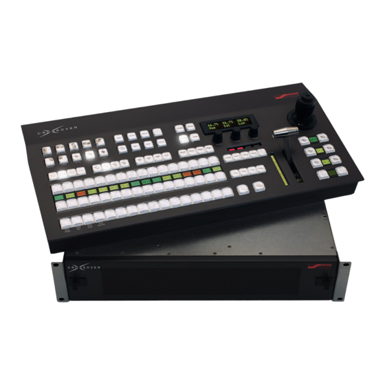
• Selects the elements (background, keys) to Control Panel Overview include in the next transition. • Selects the transition type. The CrossOver 16 provides large switcher • Performs an automatic transition or a cut. functionality in a compact form factor. 10. Fader •... -
Page 13: Control Panel Rear Connections Overview
POWER • 3 Internal Reference outputs. Removing the Frame Door Figure 1.4 CrossOver 16 Frame (Door Removed) You must remove the frame door to power on/off the 1. Power Switch frame and to access the USB port. Once you have •... -
Page 14: Menu System
Auto-follow is always active — when you press any • Double-press a knob to default the value currently button on the control panel that has a corresponding associated with that knob. menu, the menu is automatically displayed. 1–4 • Introduction CrossOver 16 User Manual (v4.0) -
Page 15: Buttons
The progress of the transition is shown on the Progress Bar to the left of the Fader handle. As the Fader handle moves from one limit to the other, the Progress Bar indicates the progress of the transition. CrossOver 16 User Manual (v4.0) Introduction • 1–5... -
Page 16: Positioner
Positioner The CrossOver 16 has a joystick positioner for positioning wipes, patterns, washes, and DVE effects. Selecting Colors Functions such as mattes, and Panel Glow have options for adjusting the appearance of a selected color. Individual adjustments for colors are: •... -
Page 17: Configuration
The format converters can convert input video from many formats to the current switcher video format. • Correcting mis-timed or drifting input signals in any of the supported video formats. The frame CrossOver 16 User Manual (v4.0) Configuration • 2–1... - Page 18 MENU 1. Press MENU. bottom of a 16:9 image to display correctly in a 4:3 video format. 2. Press the REF Wipe Pattern button. NEXT 3. Press NEXT until Fcfs is displayed. 2–2 • Configuration CrossOver 16 User Manual (v4.0)
- Page 19 • Zoom — The central portion of the video NEXT signal is zoomed to fill the display of the new 4. Press NEXT. CrossOver 16 User Manual (v4.0) Configuration • 2–3...
-
Page 20: Output Reference Sync
9. Press the left knob to save your changes. The switcher has three reference outputs that can be configured independently. 10. Press the Confrm knob to commit the change and exit the Output Sync menu. Press 2–4 • Configuration CrossOver 16 User Manual (v4.0) -
Page 21: Aspect Ratio
SYSTEM Wipe Pattern button. 4. Use the Aspect knob to select the desired NEXT 3. Press NEXT until Anclry is displayed. aspect ratio. You can choose from the following: • 4:3 • 16:9 CrossOver 16 User Manual (v4.0) Configuration • 2–5... -
Page 22: Input Bnc Configuration
• Key 2 — Clean Feed output is taken after Key 1 but before Key 2 or 3 is added. • Key 3 — Clean Feed output is taken after Key 1 and 2 but before Key 3 is added. 2–6 • Configuration CrossOver 16 User Manual (v4.0) -
Page 23: Multiviewer
• Pgm2 — Configure the Program 2 output. following: • Prview — Configure the Preview output. • PGM — Program bus output • PV — Preset bus output • 1-12 — Source inputs • M1-4 — Media-Store channels CrossOver 16 User Manual (v4.0) Configuration • 2–7... -
Page 24: Crossover Cleanswitch
You can configure display properties for each volume while the audio from the source going mnemonic label. off-air is faded to no volume. NEXT 7. Press NEXT until IPAddr is displayed. 2–8 • Configuration CrossOver 16 User Manual (v4.0) -
Page 25: Ip Address
• You do not need to connect your switcher to a 10. Use the Field knob to select the fields in the network for it to function. address. 11. Use the Value knob to modify the field value. CrossOver 16 User Manual (v4.0) Configuration • 2–9... -
Page 26: Bus Map
Customizing the Panel Glow Cancel knob to cancel the save. Panel buttons are set to a glow color which is used when the button is not selected. This glow color can be customized. 2–10 • Configuration CrossOver 16 User Manual (v4.0) - Page 27 2. Press the PERS Wipe Pattern button. During Power-Save mode, video related hardware is 3. Press the DblPrs Speed knob. not affected and video signals are still passed through the switcher. CrossOver 16 User Manual (v4.0) Configuration • 2–11...
- Page 28 DVE1 knob to select how the first 10. Press the Confrm knob to commit the DVE resource is shared between keys and the change. Press the Cancel knob to cancel the change. 2–12 • Configuration CrossOver 16 User Manual (v4.0)
- Page 29 MENU 1. Press MENU. • You can quickly turn editor control on or off by MENU MENU button, and pressing and holding the 2. Press the SYSTEM Wipe Pattern button. press PERS. CrossOver 16 User Manual (v4.0) Configuration • 2–13...
- Page 30 Next Transition Bank knob to select which GPI output bank you wish to control. Note: • Only one GPI output bank can be triggered at a time. 2–14 • Configuration CrossOver 16 User Manual (v4.0)
-
Page 31: Background Double-Press
BKGD button is double-pressed. • TrsClr — Select this option to include all on-air keyers with the next transition when the BKGD button is double-pressed. CrossOver 16 User Manual (v4.0) Configuration • 2–15... - Page 32 2–16 • Configuration CrossOver 16 User Manual (v4.0)
-
Page 33: Basic Operation
These factors include the number of media resources you CrossOver 16 User Manual (v4.0) Basic Operation • 3–1... -
Page 34: Configuring The Auto Trans Rate
AUTO TRANS button. Transitions performed with DVE Transitions the Fader are not affected. You can select from a number of pre-defined patterns and control the amount of time a DVE transition takes to complete. 3–2 • Basic Operation CrossOver 16 User Manual (v4.0) -
Page 35: Media Transitions
• Performing a DVE transition on a DVE Key with the background included does not scale the transition effect. This transition consumes the Pausing a Transition second DVE resource. You can pause a transition while it is in progress. CrossOver 16 User Manual (v4.0) Basic Operation • 3–3... -
Page 36: Keying Overview
Borders and other effects may be used to enhance 2. Select the key you wish to use. the key appearance. 3. Select the key type by pressing one of the The CrossOver 16 supports 3 keys. following: Video Layering SELF •... -
Page 37: Dedicated Key Transitions
If an immediate transition is required, or an than a luminance value or alpha signal. The color is unexpected transition needs to be performed, the dedicated key transition buttons can be used. CrossOver 16 User Manual (v4.0) Basic Operation • 3–5... - Page 38 6. Press the Init knob to initialize the chroma key. Every time the Init knob is pressed, the switcher resets all the Chroma Key parameters to their default settings. 3–6 • Basic Operation CrossOver 16 User Manual (v4.0)
- Page 39 You modify the Shadow range to cover darker areas of Value knob to select the central, • Use the or base, color for the foreground as follows: CrossOver 16 User Manual (v4.0) Basic Operation • 3–7...
- Page 40 Note that the › Increasing the Softness value increases the Shadow and translucent areas (see below) are amount of softness applied to the foreground edges and alpha channel. 3–8 • Basic Operation CrossOver 16 User Manual (v4.0)
- Page 41 Cntrl knob to select BkLuma. • Use the spilling over into the foreground (green color • Use the Value knob to change the overall brightness of Shadow, Translucent, and Transition areas as follows: CrossOver 16 User Manual (v4.0) Basic Operation • 3–9...
-
Page 42: Dve Key
Transition colors as follows: prompted to steal the DVE resource to use on › Increasing the Gain value makes the the new key. You can choose from the following: Transition area pixels more opaque. 3–10 • Basic Operation CrossOver 16 User Manual (v4.0) -
Page 43: Mattes
NEXT until WASH is displayed. • setting hue, saturation, and luminance, refer to the section “Selecting Colors” on page 1-6. 3. If the WASH knob is Off, toggle it On by pressing the WASH knob. CrossOver 16 User Manual (v4.0) Basic Operation • 3–11... -
Page 44: Fade To Black
• If the wash is turned off, the pattern does not display. • The wash pattern and the key pattern mask are shared. Any adjustments affect both patterns. • You can change the pattern size by turning the positioner. 3–12 • Basic Operation CrossOver 16 User Manual (v4.0) -
Page 45: Advanced Operation
4. Press AUTO TRANS to complete the NEXT TRANS 2. Press NEXT to cycle through the available transition. wipe modifiers. To Quickly Reset the Transition Limit Limit knob. • Double-press the CrossOver 16 User Manual (v4.0) Advanced Operation • 4–1... -
Page 46: Modifying Dve Transitions
NEXT 2. Press NEXT until Time is displayed. additional DVE effects that are not assigned to pattern buttons. 3. Use the Time knob to change the duration of the DVE transition. 4–2 • Advanced Operation CrossOver 16 User Manual (v4.0) -
Page 47: Advanced Keying
Press NEXT Note: and use the knobs to access and change other • You can change the mask size by turning the attributes. positioner. CrossOver 16 User Manual (v4.0) Advanced Operation • 4–3... - Page 48 • Use the section “Resource Sharing” on page 2-12. color. Press the Load knob to load the color. BHue, BSat, and BLum • Use the knobs until the desired color is achieved. 4–4 • Advanced Operation CrossOver 16 User Manual (v4.0)
-
Page 49: Aux Buses
Alpha knob to select the input used bus. for the key alpha. Note: • You can also select a matte color for an Aux bus. 3. Press the Alpha knob to accept the change. CrossOver 16 User Manual (v4.0) Advanced Operation • 4–5... -
Page 50: Creating An Ftp Connection
Consult with your IT department if you require assistance with creating an FTP connection. The following procedure describes how to create an FTP connection using Microsoft® Windows® XP 4–6 • Advanced Operation CrossOver 16 User Manual (v4.0) -
Page 51: Live Edit Decision Lists (Edl)
GPI output in step 5 above. • If the selected GPI output is configured as a level Both trigger, it remains in the latched state until you Stop — unlatch it. CrossOver 16 User Manual (v4.0) Advanced Operation • 4–7... - Page 52 • installation and configuration of the TSC-9902 • password: password LTC to Serial Converter, refer to your TSC-9902 documentation. 2. Copy EDL files from the switcher to your computer for use in your NLE suite. 4–8 • Advanced Operation CrossOver 16 User Manual (v4.0)
-
Page 53: Reset Options
You can also capture the state of the switcher as a user-defined default, allowing you to reset to those 10. Press the RState Save knob to save the settings at any time. new default settings. CrossOver 16 User Manual (v4.0) Advanced Operation • 4–9... - Page 54 RESET Wipe Pattern button. user-defined default values. To reset Aux buses: 1. Press and hold down AUX 1, AUX 2, AUX 3. 2. Press the RESET Wipe Pattern button. 4–10 • Advanced Operation CrossOver 16 User Manual (v4.0)
-
Page 55: Tallies
Adding, Modifying, and Removing Devices Cancel knob to cancel the reset. Press the External devices must be added to the switcher and then assigned to an input before they can be CrossOver 16 User Manual (v4.0) Advanced Operation • 4–11... - Page 56 Add knob to select the device to menu. edit. 7. Use the Device knob to select the device to 6. Press the Edit knob to display the Device assign to the selected input. Edit menu. 4–12 • Advanced Operation CrossOver 16 User Manual (v4.0)
- Page 57 5. Press NEXT until Device is displayed. with your camera. 6. Press the Device knob to display the 2. Set the camera orientation, focus, and iris Device menu. settings as required. CrossOver 16 User Manual (v4.0) Advanced Operation • 4–13...
-
Page 58: General Purpose Interface (Gpi)
Banks configured as GPI inputs are used to trigger memory recalls, transitions, and Aux bus input changes. Banks configured as GPI outputs allow your switcher to trigger actions on external devices. 4–14 • Advanced Operation CrossOver 16 User Manual (v4.0) -
Page 59: Triggering Gpi Outputs
Table 4.5 GPI Port GPI Input Mapping Trigger Triggering GPI Outputs Bank 1 Dissolve Key 1 You can trigger GPI outputs manually or automatically. Dissolve Key 2 Dissolve Key 3 Perform Auto Transition CrossOver 16 User Manual (v4.0) Advanced Operation • 4–15... - Page 60 NEXT button, the states of • While holding the all GPI outputs in the selected bank are displayed. 2. Use the RlClip knob to control whether the switcher triggers the GPI output before 4–16 • Advanced Operation CrossOver 16 User Manual (v4.0)
-
Page 61: Transition Pre-Delay
• Initiate a transition with the fader handle. The Figure 4.6 Editor Port pre-delay countdown is aborted and the transition proceeds as you move the fader Table 4.7 Editor Port Pinout handle. Input Not Connected Ground CrossOver 16 User Manual (v4.0) Advanced Operation • 4–17... - Page 62 “GVG100 Protocol Supported Commands” on page 9-2. • LiveEDL, refer to the section “Live Edit Decision Lists (EDL)” on page 4-7 • port locations, refer to the section “Frame Rear Connections Overview” on page 1-3. 4–18 • Advanced Operation CrossOver 16 User Manual (v4.0)
-
Page 63: Custom Controls
Almost any action or setting can CrossOver 16 User Manual (v4.0) Custom Controls • 5–1... -
Page 64: Inserting Special Functions
To Insert a Special Event into a Custom Control: 1. Start recording or editing your custom control where you want to insert the special event. INSERT 2. Press INSERT. 5–2 • Custom Controls CrossOver 16 User Manual (v4.0) -
Page 65: Editing Custom Controls
7. Use the Char knob to select a character for to delete. You can also use the the current position. PREV NEXT buttons. NEXT 8. Press NEXT. DELETE DELETE. • Press CrossOver 16 User Manual (v4.0) Custom Controls • 5–3... -
Page 66: Deleting Custom Controls
5. Press the Func knob. 6. Press the Confrm knob to delete the custom control. Note: • You can also delete a custom control by selecting DELETE the custom control and pressing DELETE. 5–4 • Custom Controls CrossOver 16 User Manual (v4.0) -
Page 67: Memories, Usb Storage, And Upgrades
NEXT. in the memory register and smoothly transitions between them over a user-configurable duration. 3. Use the Attrib knob to select the memory attribute you wish to set. CrossOver 16 User Manual (v4.0) Memories, USB Storage, and Upgrades • 6–1... - Page 68 • Recall — The sources that were stored in the memory are recalled and replace the currently selected source on the Program bus. This is the default setting. 6–2 • Memories, USB Storage, and Upgrades CrossOver 16 User Manual (v4.0)
- Page 69 • Recall — The key maks settings stored in the set to NoRcl. memory for the selected keyer are recalled with the memory. This is the default setting. CrossOver 16 User Manual (v4.0) Memories, USB Storage, and Upgrades • 6–3...
-
Page 70: Storing Memory Registers
2. Select the memory register you wish to recall from as follows: • If you are using Bank Mode, press a Wipe Pattern button to select a memory register in 6–4 • Memories, USB Storage, and Upgrades CrossOver 16 User Manual (v4.0) - Page 71 • Scenario 1 The source on the bus you selected will not › Input 2 is recalled to the Preset bus. change when the memory is recalled (the source CrossOver 16 User Manual (v4.0) Memories, USB Storage, and Upgrades • 6–5...
-
Page 72: Usb Storage
“Software Upgrades” on page 6-7. image dissolves to Input 3). • FTP access to the USB drive, refer to the section “Creating an FTP Connection” on page 4-6. 6–6 • Memories, USB Storage, and Upgrades CrossOver 16 User Manual (v4.0) -
Page 73: Software Upgrades
Do not turn the switcher power off during the Loading Switcher Settings upgrade. You can load switcher settings that were previously saved to a USB drive. CrossOver 16 User Manual (v4.0) Memories, USB Storage, and Upgrades • 6–7... - Page 74 This does not indicate a problem with your switcher. For More Information on... • accessing the USB port, refer to the section “Frame Overview” on page 1-3. 6–8 • Memories, USB Storage, and Upgrades CrossOver 16 User Manual (v4.0)
-
Page 75: Media-Store
• Dual — Four channels of Media-Store are named Anim. available. Each channel can contain a separate image, or Channel 1 can contain an image and an associated alpha-channel in Channel 3, and Channel 2 can contain an CrossOver 16 User Manual (v4.0) Media-Store • 7–1... -
Page 76: Loading Media By Browsing
Media-Store channel you 4. Use the left knob to select <..> to move up to wish to load images or animations to. The folder the top level of the file system. 7–2 • Media-Store CrossOver 16 User Manual (v4.0) -
Page 77: Understanding Media Numbers
Media numbers are entered using the Wipe Pattern drive, a Media Error message is displayed. You buttons. You can choose to lock the Place and Bank to specific values which allows you to quickly access a subset of images. CrossOver 16 User Manual (v4.0) Media-Store • 7–3... -
Page 78: Media-Store Attributes
You can alter the appearance of a Media-Store animations by modifying display and play Media-Store attributes can be broken down into three parameters. types; Still Attributes, Animation Attributes, and Media Transition Attributes. 7–4 • Media-Store CrossOver 16 User Manual (v4.0) -
Page 79: Animation Control
You can play an animation manually or automatically You can alter the appearance of a media transitions and also control the behavior of animation playback. by modifying display, play, and transition parameters. CrossOver 16 User Manual (v4.0) Media-Store • 7–5... -
Page 80: Saving And Reverting Attributes
(MEDIA) that you want to load a still or animation into. The image that is currently loaded into that channel is shown on the menu. NEXT 2. Press NEXT until Attrib is displayed. 7–6 • Media-Store CrossOver 16 User Manual (v4.0) -
Page 81: Calibration And Diagnostics
5. Press the MENU and RESET buttons positioner with X, Y and Z limits. at the same time to end the test. CrossOver 16 User Manual (v4.0) Calibration and Diagnostics • 8–1... - Page 82 RAM test. 5. Press the Reboot knob to run the test. The switcher runs the test and then reboots. 8–2 • Calibration and Diagnostics CrossOver 16 User Manual (v4.0)
-
Page 83: Error Messages
Your switcher control panel is connected Connect your switcher control panel to Panel/Frame Mismatch to the wrong frame type (e.g. Crossover 16 the proper frame and re-start the switcher. panel connected to a Crossover 6 frame). Your switcher requires a Panel Module Allow the PMC upgrade to proceed. - Page 84 8–4 • Calibration and Diagnostics CrossOver 16 User Manual (v4.0)
-
Page 85: Specifications
• Maximum differential input voltage: ±5V • Input Equalization (SD): 275m • Differential output voltage (5V circuit): 3.2V • Input Equalization (HD): 110m Typical across a 100 Ω load (2.3V for 3.3V circuit) CrossOver 16 User Manual (v4.0) Specifications • 9–1... -
Page 86: Gvg Editor Input Mapping
• Duration: NTSC: 4.7us ±0.1 us PAL: 4.7us ±0.2us • Rise Times (10-90%): 54ns ±20ns • Duration: 593ns ±40ns GVG Editor Input Mapping Table 9.1 CrossOver 16 Input Mapping The following table lists the GVG Editor – switcher input mapping: Table 9.1 CrossOver 16 Input Mapping... - Page 87 — — Included for GVG100 Write Lamp Status spec completeness only. Write Button Press Both <button> Send Mem To Editor — Not yet implemented Load Mem From Editor — Not yet implemented CrossOver 16 User Manual (v4.0) Specifications • 9–3...
- Page 88 Not supported 3D Position Z — 0x25 Not supported 3D Border Softness — 0x26 Not supported 3D Border Width — 0x27 Not supported Key Clip Keyer 0x08 DSKs Key Gain Keyer 0x09 DSKs 9–4 • Specifications CrossOver 16 User Manual (v4.0)
- Page 89 Next Trans Is Bkgd — 0x48 Turning OFF results in a protocol error. Next Trans Is Key 1 — 0x49 Turning OFF results in a protocol error. 0x4A Turning OFF results in a protocol error. CrossOver 16 User Manual (v4.0) Specifications • 9–5...
- Page 90 Key Invert Keyer 0x44 Key Mask Keyer 0x45 — 0x47 Toggles between memory mode and Memory Mode Toggle pattern mode. Next Trans Is Bkgd — 0x48 Next Trans Is Key 1 — 0x49 9–6 • Specifications CrossOver 16 User Manual (v4.0)
- Page 91 Table 9.5 GVG100 Supported Buttons Name MLE/Keyer Byte code Notes 0x4A Key Selfkey Keyer 0x4C Key Autokey Keyer 0x4D Key Chromakey Keyer 0x4E Editor Enable — 0x4F Editor control is always enabled. CrossOver 16 User Manual (v4.0) Specifications • 9–7...
- Page 92 9–8 • Specifications CrossOver 16 User Manual (v4.0)
Need help?
Do you have a question about the CrossOver 16 and is the answer not in the manual?
Questions and answers