Table of Contents
Advertisement
Advertisement
Table of Contents

Summary of Contents for Logic Six LGSIX/01
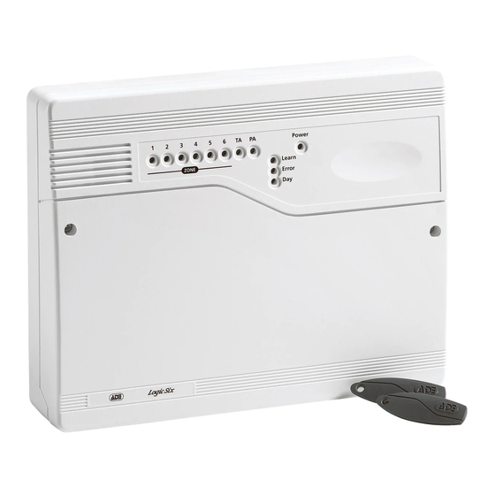
- Page 1 1 2 3 4 5 6 TA PA ZONE Learn Error /! mini ccenta LGSIX/01 Logic Six panel with two pre learnt Keyfobs The above intruder system is designed to comply with the installation requirements of BS 4737 1986/87. 4188-753 issue 1_1/03...
-
Page 2: Table Of Contents
Engineering information Features Contents Features - - - - - - - - - - - - - - - - - - - 2 ÿ 6 Security zones Installation Design - - - - - - - - - - - - - - 3 Fixing the control panel - - - - - - - - - - - 3 ÿ... -
Page 3: Installation Design
Logic Six intruder system Installation Design Fixing the control panel The purchase of this alarm system represents a Caution: When positioning the control major step forward in the protection of the panel ensure that it is located in a dry property and its occupants. -
Page 4: Wiring The System
Engineering information Fit the panel to the wall with suitable There are three fuses mounted on the circuit fixings. Ensure the wall surface is flat to board, all are 20mm quick blow. prevent base distortion. There are F1 1.6A - to protect the +ve line of 12V battery cable entry holes provided in the rear F3 1A - to protect the Speaker 13V supply of the base and around the outside... -
Page 5: Security Zones
Logic Six intruder system Security zones Panel Board TAMP +13V 0V Terminal block is not supplied Door Contact Tamp All unused zones Alarm must have links fitted to disable the zone. Door Contact Note: The panel is supplied with wire links for unused zones. All unused zones must have links fitted to disable the zone. -
Page 6: Pa Circuit
Engineering information PA circuit Any quantity of normally closed type personal attack button may be wired in series and then connected to the PA circuit. Operational in Day and Set, the PA circuit will cause a full alarm condition when activated. PA is indicated on the control panel as PA. -
Page 7: Extension Speaker
Logic Six intruder system Extension speaker Extension speaker may be connected to the loudspeaker terminals to produce high volume alarm tones and low volume entry / exit fault tones. Panel Board VOLUME STROBE BELL 16 Ohms Extension Speaker A 16 ohms extension speaker may be wired across the speaker terminals. Mounted in convenient position within the installation the extension speaker will reproduce all of the alarm tones generated by the control panel. -
Page 8: External Siren Output (Bell Box)
Engineering information External siren Output (Bell box) The external siren (bell box) is usually installed in a high position from where the siren could be seen and heard. Terminal T A D B are for connecting to the external siren. These terminals provide a power/hold-off supply, sounder trigger and tamper circuit to protect the external siren housing. -
Page 9: 13V Supply Output
Logic Six intruder system Panel Board # Terminal block STROBE BELL is not supplied STROBE STROBE Sonade Sonade Where self contained / powered sounders are used, carefully follow the manufacturers instructions, match each of the terminals to those above. 13V Supply output The 13V output is to power detectors which require a voltage supply (PIR detectors etc). -
Page 10: Factory Set Condition
Engineering information Factory set condition Zone Function The following are definitions of zone functions: Keyfob 1 and 2 (supplied) - Learnt Keyfobs 3 to 8 (optional) - - Require learning Timed : This function would be used to protect the main entry/exit door of the entry route. External siren Bell Duration 20 minutes External siren Bell Delay - - No delay Time inhibited (Walk through) : This is a zone... -
Page 11: First Power Up
Logic Six intruder system First Power up Note: If you do not withdraw the keyfob after it is recognised by the panel then Before power up fit the top cover on to the base you run the risk of entering an undesired and connect the speaker wires. -
Page 12: Testing The System
Engineering information Testing the system Programs Complete the wiring of the system and then: The panel offers Full Set or selectable Part Set routine and programmable entry time. As default ÿ Program the panel. the panel is set for Full Set and an Entry time of ÿ... -
Page 13: Walk Tests
Logic Six intruder system Walk tests Alarm tests The walk test function allows each detector to be The alarm test function allows you to test the checked in order to verify that they are Strobe, Siren (Bell), Low and High volume functioning correctly. -
Page 14: How To Learn New Keyfobs
Engineering information How to learn new keyfobs Using a recognised learnt keyfob panel can learn further keyfobs. A total of 8 keyfobs are recognised by a Panel. You may want to do this if you have acquired additional keyfobs. Using these procedures the panel will still memorise previously learnt keyfobs. -
Page 15: How To Re-Learn All Keyfobs
Logic Six intruder system How to re-learn all keyfobs Using a recognised learnt keyfob Panel can re-learn up to 8 keyfobs. You may want to do this after a keyfob is lost or stolen and you want to prevent the use of it to operate the system. -
Page 16: How To Learn Keyfobs If Non Are Recognised
Engineering information How to learn keyfobs if none are recognised You will only need to learn keyfobs in this manner if no keyfobs are recognised by the Panel. Panel learn up to 8 keyfobs following power up of the intruder system. You must have all the keyfobs to be learnt available. -
Page 17: Re-Arm
Logic Six intruder system NVM Error Alarm Cycle Counter A Non Volatile Memory NVM error indication An alarm cycle is considered as the duration of is given by a flashing Error LED. If an NVM an alarm from trigger to the end of 20 minutes error occurs then you will need to re-learn all the operation of the external siren. -
Page 18: Faults
Engineering information removing the control panel covers. Faults Fault conditions are often the result of minor Where normally open and closed installation errors or misinterpretation of the detectors are being used these must equipment being installed. The following points be wired to a zone in the manner outline the most common installation and shown. -
Page 19: Specification
Logic Six intruder system Total Current 1A when supported by a Specification Output fully charged battery Indicators on Zone 1-6 (red), Tamper - Mains Supply 230V (+/-10%) 50Hz Control panel TA (amber), Personal Voltage max load 0.2A Attack-PA, Power, Learn Ambient 0°C to 40°C... -
Page 20: Servicing Organisation Details
Zone 4 Zone 5 Zone 6 ED&S The Arnold Centre The Logic Six panel conforms to the Paycocke Road requirements of the European R&TTE directive 1999/5/EC and carries the CE mark. This Basildon Essex product is intended for use in the UK. -
Page 21: Operating Instructions
Intruder alarm system Operating Instructions Power 1 2 3 4 5 6 TA PA ZONE Learn Error /! mini ccenta Servicing organisation details Servicing organisation (Installer) name: ______________________________________________ Telephone number: _______________________________________________________________ Date of installation: _______________________________________________________________ Account number: _________________________________________________________________... - Page 22 Operating instructions System installation Keyfobs This booklet tells you how to operate your To operate the alarm system you will need the intruder alarm system. To simplify this booklet keyfobs supplied with the panel. These keyfobs we have assumed that the alarm system has been are recognised by the panel and will operate installed by a professional intruder alarm system your system.
- Page 23 Logic Six intruder system Personal Attack Power Indicator If you are under threat, or are being attacked, The Power indicator on the control panel will you can activate the alarm by operating the light whenever the mains power supply is personal attack buttom in your system.
- Page 24 Operating instructions How to Set the system When you leave your premises you will need to set (or turn on) the intruder alarm system. Before setting the system you should ensure that the premises have been completely vacated and that all doors and windows are closed.
- Page 25 Logic Six intruder system How to Unset the system When you enter your premises you will need to unset (or turn off) the system. If your system had gone into alarm then be aware that intruders may be in the premises. Seek assistance before investigating the cause of the alarm and unset the system.
- Page 26 Operating instructions How to part set the system If your installer has programmed your system for part set operation you will be able to set some zones of the system while others remain unset. Part set operation is often used at night time, and it will permit you to freely walk around the bedrooms while the living area and outside doors are protected.
- Page 27 Logic Six intruder system Entry time:________________ Area Zone name Full set Part Set protected Zone 1 Zone 2 Zone 3 Zone 4 Zone 5 Zone 6 O = Omited T = Timed (Entry/Exit - Zone) TI = Time Inhibited (Access zone to keypad)
- Page 28 Operating instructions The Logic Six panel conforms to the requirements of the European R&TTE directive 1999/5/EC and carries the CE mark. This product is intended for use in the UK. 4188-753 issue 1_1/03...
Need help?
Do you have a question about the LGSIX/01 and is the answer not in the manual?
Questions and answers