
Subscribe to Our Youtube Channel
Summary of Contents for Hammer Engines GmbH RC 90+
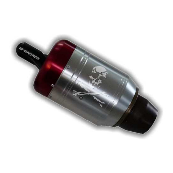
- Page 1 IQ-Hammer Series Instruction Manual RC Model jet Engines 90+ / 130+ / 160+ / 170+ / 180+ © 2010 Hammer Engines GmbH Ottensooser Str.50c 91239 Henfenfeld Germany Tel.: +49 (0)9151 / 2841 http://www.iq-hammer.com Layout: Stefan Schmitz...
-
Page 2: Table Of Contents
Hammer Engines GmbH / IQ-Series / Instruction Manual Table of contents Introduction Safety Precautions Technical Specifications Installation plan Operational checklist 9-10 ECU and IO-board Input - Terminal - EDT Menu structure and flow Status display / Turbine status and Display symbols... -
Page 3: Introduction
Hammer Engines GmbH / IQ-Series / Instruction Manual Introduction The „IQ-Hammer“ RC model jet engines by Hammer Engines have the same functional principles as their big counterparts. A high performance compressor compresses the ingested air, which is then heated by fuel flame in the combustion chamber and the heat causes the air to expand rapidly, enabling it to drive an axial turbine rotor, which in return drives the aforementioned compressor via a shaft. -
Page 4: Safety Precautions
Hammer Engines GmbH / IQ-Series / Instruction Manual Safety Precautions Welcome to the Jet Age of RC model aircrafts! Never forget: Operating a jet engine like the IQ-Hammer can be dangerous. An aircraft model equipped with the IQ-Hammer can reach speeds of more than 400 km/h (250 mph) and temperatures up to 500 °C (930 °F) at the engine housing and up to 750 °C (1380 °F) at the... - Page 5 in bad weather with low clouds or fog. Never fly directly against the sunlight – otherwise you might lose visual contact with your model. To avoid collisions with manned or unmanned aircraft, land your model immediately if an aircraft is approaching. Persons and animals must keep the following minimum distance to the jet engine (see also the figure on page 6): In front of the engine: 1 m (3 ft) At the sides of the engine: 12 m (36 ft)
- Page 6 Hammer Engines GmbH / IQ-Series / Instruction Manual Only test the jet engine at suitable places outdoor and observe the applicable laws and regulations. Always enforce the proper minimum safe distance from the turbine: Never look straight into the exhaust jet and never touch it or the exhaust stream with your hands.
-
Page 7: Technical Specifications
Hammer Engines GmbH / IQ-Series / Instruction Manual technical specifications IQ-Hammer Series... -
Page 8: Installation Plan
Hammer Engines GmbH / IQ-Series / Instruction Manual installation plan... -
Page 9: Operational Checklist
Hammer Engines GmbH / IQ-Series / Instruction Manual Checklist for the first time of Operation of the IQ-Hammer turbine Install and connect the components according to the installation plan (see page 14). Pay special attention to the correct connection of the FUEL valve and to a proper plumbing of the tubes without kinking them. - Page 10 Open the fuel tank ventilation, then fill the fuel tank(s) with fuel containing approximately 5 % of AeroShell 500 or AeroShell 560 oil Have a CO2 fire extinguisher at hand! Turn on the R/C transmitter, and then turn on the receiver. Place your aircraft model with the nose into the wind.
-
Page 11: Ecu And Io-Board
Hammer Engines GmbH / IQ-Serie / Instruction Manual ECU und IO-circuitry ECU Connector layout IO-Board In order to extend the Input/ouput ports as well as the interface you can connect the IO-Board in between the Electronics and the Terminal and place it at an accessible location inside your airframe. -
Page 12: Input - Terminal - Edt
Hammer Engines GmbH / IQ-Serie / Instruction Manual Electronic Data Terminal – EDT Instructions All parameters relevant to this operation of the turbine will be transmitted to the EDT via the Terminal where they are being stored. The following will give you an overview of the complete menu structure. -
Page 13: Menustructure And Flow
Hammer Engines GmbH / IQ-Serie / Instruction Manual MENUSTRUCTURE And flow Access Sub menus by pressing Exit the Submenu without storing any changes by pressing... -
Page 14: Status Display / Turbine Status And Display Symbols
Hammer Engines GmbH / IQ-Serie / Instruction Manual Status Readout on EDT You can browse through the respective status readout screens by pressing the -buttons. Once switched on the following Screen 1 will be displayed by default: Temperature RPMx100 / Throttle-Channel (%) Status Pump- or. -
Page 15: Status Readouts / Start Procedure
Hammer Engines GmbH / IQ-Serie / Instruction Manual Status readouts / the order of readouts on this page corresponds to the order they occur in during the startup sequence Turbine off, waiting for Standby STANDBY Standby – waiting for Startup Sequence. (Throttle stick and throttle trim at 0%, then both... -
Page 16: Status Readouts / Explanation Of The Status Symbols
Hammer Engines GmbH / IQ-Serie / Instruction Manual STATUS AUTO Turbine in automatic mode EMERGENCY Emergency mode – the turbine will be controlled by pump voltage alone SLOW DOWN Turbine off – waiting for standstill COOL DOWN The turbine is actively being cooled by spooling up... -
Page 17: Menu 1 - Settings
Hammer Engines GmbH / IQ-Serie / Instruction Manual Menu and Settings ↓ To enter the max revolution speed of the turbine ↓ To enter the min revolution speed of the turbine ↓ This parameter specifies the acceleration/throttle-up time (more thrust) and deceleration/throttle-downtime (less thrust) of the engine. - Page 18 Hammer Engines GmbH / IQ-Serie / Instruction Manual This parameter specifies the maximum allowed voltage [V] for the fuel pump. Do not confuse this value with pump-voltage at 100% throttle. This value is only being used in order to identify failure. Should this limit be exceeded the pump will be switched of automatically! The set voltage should be a tad above 100% throttle V.
-
Page 19: Menu 2 - Teaching The Transmitter
Hammer Engines GmbH / IQ-Serie / Instruction Manual ↓ The ECU must be calibrated to your transmitter. Please follow these instructions: 1. THRO. LO/TRIM LO: Set throttle and throttle trim to minimum -> press 2. THRO. LO/TRIM HI: Set throttle trim to max, leave throttle stock at minimum ->... -
Page 20: Menu 3 - System
Hammer Engines GmbH / IQ-Serie / Instruction Manual ↓ Input the minimum and maximum battery voltage. This will determine at what thresholds the unit will read out Battery Full or Battery Empty. ↓ Choose the language you want the unit to be set to. -
Page 21: Menu 4 - Gps & Airspeed
Hammer Engines GmbH / IQ-Serie / Instruction Manual Activates the Telemetry transmitter (TRX-2400). Amount of Data packets per time unit (OFF/1x/2x/3x), channel transmitted on (COM-CHANNEL 0-10) and the address of the Graphic-Telemetry (0-10000). Please refer to the corresponding manuals for further information. -
Page 22: Menu 5 - Test Functions
Hammer Engines GmbH / IQ-Serie / Instruction Manual GPS-Speed /Altitude GPS-V: Speed in km/h GPS-ALT: Current altitude above 0 in meters Maximum radial distance and speed G-MAX-R: Maximum recorded distance from point of start-up G-MAX-V: Maximum recorded Groundspeed (GPS) Maximum/Minimum Altitude... - Page 23 Hammer Engines GmbH / IQ-Serie / Instruction Manual ↓ (3) This option has been removed due to the use of a ceramic burner. ↓ (4) FUEL VALVE TEST Using the fuel valve can be operated manually. ↓ (5) SMOKER-VALVE TEST Using the smoker valve can be operated manually.
-
Page 24: Menu 9 - Mastermode
Hammer Engines GmbH / IQ-Serie / Betriebsanleitung (5) STARTER TEST Using the starter motor can be operated manually. ___________________________________________________________________________ ↓ IMPORTANT! Using this menu you can adjust all vital parameters of your turbine. These settings are meant for experts only. This menu is disabled by... -
Page 25: Course Of Events - Calibration - Adjustment - Fail Safe
Hammer Engines GmbH / IQ-Serie / Instruction Manual Radio equipment Throttle The turbine is operated by the throttle channel: • Startup initiation • RPM / thrust control during flight • Shut down You have to teach the transmitter before operating the turbine for the first... -
Page 26: Radio Equipment - Fail Safe - Auxiliary Channel
Hammer Engines GmbH / IQ-Serie / Instruction Manual FAILSAFE TIMEOUT: Time between initiation of failsafe trust and complete shutdown, should the glitch or bad command continue. FAILSAFE THRUST: Once the FAILSAFE DELAY has passed the turbine will go to this preset rpm. -
Page 27: Technical Data - Accessories
Hammer Engines GmbH / IQ-Serie / Instruction Manual Specifications • Powerful RISC Microcontroller • Simple programming using FLASH MEMORY • Modern USB PC-connection • Kero start • Can be operated on a single channel • Turbine startup using GSU for models with multiple engines •... -
Page 28: Notes
Hammer Engines GmbH / IQ-Serie / Instruction Manual Notes:... -
Page 29: Possible Error Messages
Hammer Engines GmbH / IQ-Serie / Instruction Manual Possible Error messages Errors messages during startup: RPM < 2.000 DURING WARMUP/ VORHEIZEN REASON: Turbine RPM dropped below 2.000 during warm-up CAUSE: Starter voltage is too low during warm-up (Menu 9.16), starter failure, turbine stuck RPM <... - Page 30 Hammer Engines GmbH / IQ-Serie / Instruction Manual CALCULATED MAX PUMP VOLTAGE TOO HIGH REASON: Pump voltage needed for full throttle operation exceeds preset limit (Menu 1.6) CAUSE: The max pump voltage has been set too low, the corrective factor has been set too high (Menu 9.6), pump voltage at calibration RPMS is too high (Points towards a fuel...
- Page 31 Hammer Engines GmbH / IQ-Serie / Instruction Manual GENERAL ERROR MESSAGES PUMPDRIVER FAILURE REASON: The max allowed pump load (Menu 1.6) has been exceeded CAUSE: Pump blocked by contamination; pump disconnected -> User error BATTERY VOLTAGE to low REASON: Turbine battery voltage dropped below limit set in Menu 3.1 CAUSE: Battery empty or defective ->...
-
Page 32: Purchase Agreement, Warranty Etc
PURCHASE AGREEMENT, FULL ASSUMPTION OF LIABILITY AND INDEMNITY AGREEMENT Buyer purchases from Hammer Engines GmbH, a Limited Liability Company or from one of Hammer Engines GmbH authorized dealers, a MINIATURE TURBOJET ENGINE for model aircraft, cars or boats ("Model Engine") for the invoice price, accompanying this sale, and Buyer and Vogelsang Aeroscale agree to all of the following terms and conditions: 1. - Page 33 Hammer Engines GmbH shall not be liable for its willful misconduct. s Hammer Engines GmbH hall not be liable based on any theory in strict liability in tort. Hammer Engines GmbH shall not be liable for any alleged breach of warranty, whether express or implied, of any nature whatsoever, whether a warranty of fitness for a particular use, merchantability, or otherwise.
- Page 34 / end-user. 2) Upon request from Hammer Engines GmbH, the Buyer must prove the date of the original purchase of the Model Engine by a dated bill of sale or dated itemized receipt.
- Page 35 16) This limited warranty allocates the risk of failure of the Model Engine between the Buyer and Hammer Engines GmbH or one of its dealers. The allocation is recognized by the Buyer and is reflected in the purchase price of the Model Engine.
Need help?
Do you have a question about the RC 90+ and is the answer not in the manual?
Questions and answers